
Manual

GE
Data Sheet
12V MicroTLynx
TM
12A: Non-Isolated DC-DC Power Modules
4.5Vdc –14Vdc input; 0.69Vdc to 5.5Vdc output; 12A Output Current
May 2, 2013 ©2013 General Electric Company. All rights reserved. Page 4
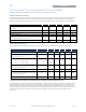
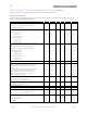
Electrical Specifications (continued)
Parameter Device Symbol Min Typ Max Unit
Switching Frequency All f
sw
⎯
500
⎯
kHz
Frequency Synchronization
Synchronization Frequency Range 520 600 kHz
High-Level Input Voltage All V
IH
2.5 V
Low-Level Input Voltage All V
IL
0.8 V
Input Current, SYNC V
SYNC
=2.5V I
SYNC
1 mA
Minimum Pulse Width, SYNC All t
SYNC
250 ns
Minimum Setup/Hold Time, SYNC
2
All t
SYNC_SH
250 ns
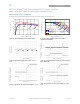
Dynamic Load Response
(dIo/dt=1A/μs; V
IN
= V
IN, nom
; T
A
=25°C)
Load Change from Io= 50% to 100% of Io,max; 1μF
ceramic// 10 μF ceramic
Peak Deviation All V
pk
⎯
360 mV
Settling Time (Vo<10% peak deviation)
All t
s
⎯
50
⎯
μs
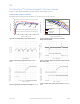
(dIo/dt=1A/μs; V
IN
= V
IN, nom
; T
A
=25°C)
Load Change from Io= 100% to 50%of Io,max: 1μF
ceramic// 10 μF ceramic
Peak Deviation All V
pk
⎯
400 mV
Settling Time (Vo<10% peak deviation) All t
s
⎯
50
⎯
μs
2
To meet set up time requirements for the synchronization circuit, the logic low width of the pulse must be greater than 100 ns wide.
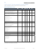
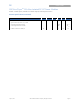
General Specifications
Parameter Min Typ Max Unit
Calculated MTBF (I
O
=0.8I
O, max
, T
A
=40°C) Telcordia Issue 2 Method 1 Case 3 16,250,892 Hours
Weight
⎯
3.68 (0.130)
⎯
g (oz.)