
User guide

GE
Data Sheet
12A Digital SlimLynx
TM
Open Frame: Non-Isolated DC-DC Power Modules
3Vdc –14.4Vdc input; 0.45Vdc to 5.5Vdc output; 12A Output Current
February 19, 2014 ©2014 General Electric Corporation. All rights reserved. Page 35
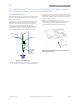
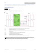
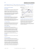
Example Application Circuit
Requirements:
Vin: 12V
Vout: 1.8V
Iout: 9A max., worst case load transient is from 6A to 9A
ΔVout: 1.5% of Vout (27mV) for worst case load transient
Vin, ripple 1.5% of Vin (180mV, p-p)
CI1 Decoupling cap - 1x0.047μF/16V ceramic capacitor (e.g. Murata LLL185R71C473MA01)
CI2 2x22μF/16V ceramic capacitor (e.g. Murata GRM32ER61C226KE20)
CI3 470μF/16V bulk electrolytic
CO1 Decoupling cap - 1x0.047μF/16V ceramic capacitor (e.g. Murata LLL185R71C473MA01) + 0.1uF/16V 0402size
ceramic capacitor
CO2 1 x 47μF/6.3V ceramic capacitor (e.g. Murata GRM31CR60J476ME19)
CO3 1 x 330μF/6.3V Polymer (e.g. Sanyo Poscap)
CTune 2700pF ceramic capacitor (can be 1206, 0805 or 0603 size)
RTune 221 ohms SMT resistor (can be 1206, 0805 or 0603 size)
RTrim 10kΩ SMT resistor (can be 1206, 0805 or 0603 size, recommended tolerance of 0.1%)
Note: The DATA, CLK and SMBALRT pins do not have any pull-up resistors inside the module. Typically, the SMBus master
controller will have the pull-up resistors as well as provide the driving source for these signals.
RADDR0
DATA
SEQ
VS-
RADDR1
GND
Vin+
CI3
CO3
A
DDR0
VOUT
VS+
GND
TRIM
CTUNE
RTUNE
RTrim
VIN
CO1
CI1
Vout+
ON/OFF
SMBALRT#
MODULE
PGOOD
A
DDR1
SIG_GND
SYNC
CI2
CO2