
Installation Guide

Installation GuideDaintree
®
Networked Wireless Thermostat (WTS10)
5
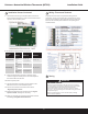
Joining the Zigbee Network
After successfully completing the Installation Test the WTS10
is ready to communicate with the Daintree Wireless Area
Controller (WAC) and be commissioned and congured using
the ControlScope Manager (CSM) web-based application. The
thermostat automatically tries to join the WAC network every
5 minutes. The WAC must be commissioned and Add New
Devices must be initiated on the WAC before the thermostat
can join the ZigBee wireless network.
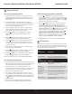
For information about conguring the thermostat using
CSM, see the on-line help.
Once the thermostat is joined, it ignores its built in schedules.
The WAC passes conguration information like set point, heat/
cooling mode, lock levels etc. at the start of each CSM schedule.
If the thermostat loses communication with the WAC the
following things will happen: (1) Thermostat continues to use
the existing conguration set by the WAC. (2) Keypad automatically
unlocks after 30 minutes to allow manual changes. (3) If remote
temperature sensor(s) are enabled, and the thermostat does not
receive a remote temperature report within 15 minutes, it will
switch to its built-in temperature sensor.
Current declares that the radio equipment type (WTS10)
complies with Directive 2014/53/EU
Full declaration text available at: www.LED.com
Max. radiated power: <10 dBm. Frequency: 2405 - 2475 MHz
Power Supply 24VAC, 50Hz
Output 3A max, 1A each terminal
Operating
Environment
32°F to 113°F (0°C – 45°C). Indoor use only
Compliance ETL listed, FCC ID: D12CT-EM2606, IC ID:
1700A-CT-EM2606
Radio 2405 ~ 2475MHz
Properties Transmit Power max 10dbm
Fahrenheit or Celsius
Display range: 14°F – 99°F (5°C – 37°C)
Temperature Display resolution: 1°F (1°C)
Measurements Setting range: 45°F – 90°F (7.0°C – 32.0°C)
Setting resolution: 1°F (0.5°C)
Accuracy: +/- 1°F @ 75°F
Switching differential 1st stage:
User selectable
• 0.5°F (default), 1.0°F, 2.0°F
(0.25°C, 0.5°C, 1.0°C)
Switching differential 2nd stage:
Fixed 2°F (1°C)
Switching differential 3rd stage:
Control Fixed 2°F (1°C)
Operational differential: Less than +/- 2°F
Control timing:
• Compressor short cycle timer – 5 min
Residual cooling fan delay:
User selectable
• 0 (disabled), 30, 60, 90 sec
• Default = 60 sec
Control Switches:
• Latching relay, 2A max load per relay
Relays:
• 1st stage/Aux heating control
• 2nd stage/Emergency heating control
• Fan Control
Switching • Heating/Cooling O/B control, 3rd stage
Circuit conventional heat control
• 1st stage cooling control / 1st stage
heat-pump heating control
• 2nd stage cooling control / 2nd stage
heat-pump heating control
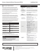
Specications
Current Certication
Operating Environment
32°F to +113°F (0°C – 45°C)
Indoor Use Only
Radio Properties
2405 ~ 2475MHz
Transmit Power max 10dbm
Compliance
Radio Equipment Directive
2014/53/EU
Power Supply 24VAC, 50Hz
These instructions do not purport to cover all details or variations in equipment nor to provide for every possible contingency to be met in connection with installation, operation
or maintenance. Should further information be desired or should particular problems arise which are not covered sufciently for the purchaser’s purposes, the matter should be
referred to GE Current, a Daintree company.
www.gecurrent.com
© 2021 Current Lighting Solutions, LLC. All rights reserved. GE and the GE monogram are trademarks of the
General Electric Company and are used under license. Information provided is subject to change without notice.
All values are design or typical values when measured under laboratory conditions.
DT103 (Rev. 05/25/2021
CAUTION
RISK OF EXPOSURE IF BATTERY IS REPLACED BY AN
INCORRECT TYPE. DISPOSAL OF USED BATTERIES
ACCORDING TO THE INSTRUCTIONS.
WTS10