
Installation Instructions
20 31-7000091 Rev. 2
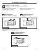
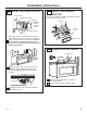
OUTSIDE BACK EXHAUST
(Horizontal Duct)
PREPARING THE REAR WALL
FOR OUTSIDE BACK EXHAUST
C1
INSTALLATION OVERVIEW
C1. Prepare Rear Wall
C2. Attach Mounting Plate to Wall
C3. Prepare Top Cabinet
C4. Adjust Blower
C5. Mount The Oven
Installation Instructions
C
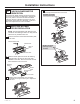
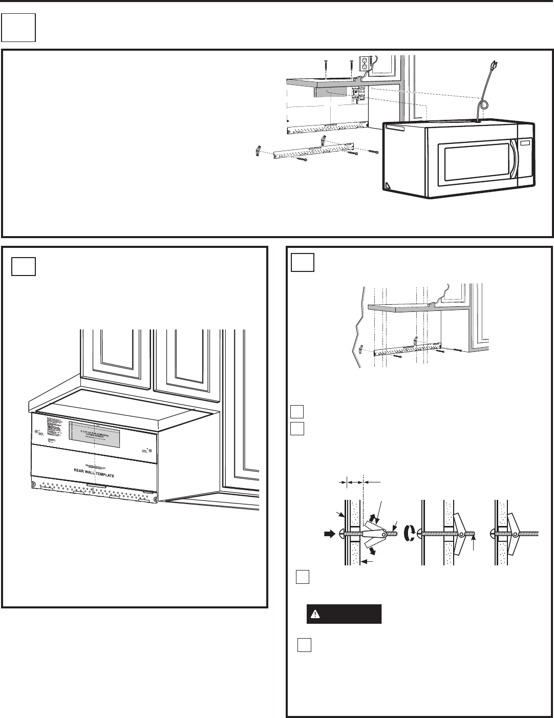
ATTACH THE MOUNTING
PLATE TO THE WALL
C2
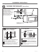
Attach the plate to the wall using toggle bolts and wood
screw. At least one wood screw must be used to attach
the plate to a wall stud.
Remove the toggle wings from the bolts.
Insert the bolts into the mounting plate through
the holes designated to go into drywall and reattach
the toggle wings to
3
»4ƎRQWRHDFKEROW
1
2
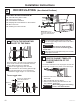
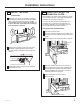
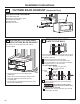
You need to cut an opening in the rear wall for
outside exhaust.
•
Read the instructions on the REAR WALL
TEMPLATE.
• Tape it to the rear wall, lining up with the holes
previously drilled for holes A and B in the
mounting plate.
• Cut the opening, following the instructions of the
REAR WALL TEMPLATE.
A
C
D
B
Wall
Mounting
Plate
Spacing for Toggles More
Than Wall Thickness
Toggle
Bolt
Toggle Wings
To use toggle bolts:
Bolt
End
Insert the toggle wings into the holes in the wall
to mount the plate and place the mounting plate
against the wall.
CAUTION
Be careful to avoid pinching
fingers between the back of the
mounting plate and the wall.
Tighten all bolts. Pull the plate away from the wall
to help tighten the bolts.
3
4
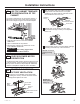
CUT HOLE THROUGH REAR WALL FOR EXHAUST ADAPTOR
12"
4"
NOTE: IT IS VERY IMPORTANT TO
READ AND FOLLOW THE DIRECTIONS
IN THE INSTALLATION INSTRUCTIONS
BEFORE PROCEEDING WITH THIS
REAR WALL TEMPLATE.
This Rear Wall Template serves to position the bottom
mounting plate and to locate the horizontal exhaust
outlet.
1. Use a level to check that the template is positioned
accurately.
2. Locate and mark at least one stud on the left or
right side of the centerline.
NOTE:
It is important to use at least one wood
screw mounted firmly in a stud to support the weight
of the microwave. Mark two additional, evenly spaced
locations for the supplied toggle bolts.
3. Drill holes in the marked locations. Where there is
a stud, drill a 3/16" hole for wood screws. For holes
that do not line up with a stud, drill 5/8" holes for
toggle bolts.
NOTE::
DO NOT INSTALL THE MOUNTING PLATE
AT THIS TIME.
4. Remove the template from the rear wall.
5. Review the Installation Instruction book for your
installation situation.
Darle vuelta a la hoja para consultar la
versión en Español.
CAUTION - IF EXHAUST ADAPTOR IS POSITIONED OUTSIDE
RECOMMENDED DIMENSION, GREASE-LADEN AIR WILL
DISCHARGE INTO HOUSE STRUCTURE
30” MINIMUM WIDTH REQUIRED
REAR WALL TEMPLATE
F. CUT OUT FOR HORIZONTAL
OUTSIDE EXHAUST
Locate and mark holes to align with holes in the
mounting plate.
IMPORTANT:
LOCATE AT LEAST ONE STUD ON EITHER SIDE OF
THE CENTERLINE.
MARK THE LOCATION FOR 2 ADDITIONAL, EVENLY
SPACED TOGGLE BOLTS IN THE MOUNTING PLATE
AREA.
Trim the rear wall template along the dotted line.
3/8" TO EDGE
C
A
C
D
B
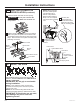
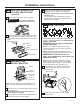
NOTES:
- 13” Max Cabinet Depth
- 15” deep cabinets require additional steps using
an additional installation kit: JX36BUMP
OPTION 1
OPTION 2
STEP 1:
Installer uses bracket to make 2 marks. First
mark is made by using the stampled slot in bracket.
Second mark is made on the ouside edge of bracket.
STEP 2:
Installer moves bracket to the other side of
the cabinets and makes 2 more marks. Marks are the
same as STEP 1, just opposite side.
STEP 4:
Make a mark here, along
inside bottom of the
stamped slot provided.
Make a mark
here,
even with
bottom of
stamped
slot
Make a mark here, along
inside bottom of the
stamped slot provided
(same as Step 1).
Make a
mark here,
even with
bottom of
stamped
slot
Horizontal line
A
C
D
B
A
C
D
B