
Architect and Engineering Manual


geappliances.com
11
UNIT AND INSTALLATION NOTES
The unit is a one-piece package system that fits directly
into a closet enclosure. Once the drain Insta-Platform
™
(RAVDPLAT) has been installed, the chassis can be
positioned on the drain platform and pushed towards
the exterior wall. The chassis will drop down slightly
into the platform, securing it in place and engaging
the gasket on the wall plenum (RAVWPT15). Power,
thermostat, and duct connections can then be made.
A 10"-diameter flange on the top of the unit is used
to connect to field-supplied, insulated, flexible or rigid
transition duct with an adjustable ring clamp.
Flexible duct may be used for transitions only. Rigid
duct must be used for 90-degree bends and tees.
Do not use flexible duct for unsupported runs of five
feet or more.
POWER CONNECTION KIT
All AZ95 series vertical units are equipped with universal
heaters that are capable of different heater outputs.
Heater output is determined by which unique direct
connect power kit is being used. This increases the
flexibility of a chassis where various heating requirements
may need to be met at a site. This power connection is
the only means of supplying power to the AZ95 chassis.
Please reference the chart on page 18 to determine the
appropriate power connection kit for your project.
RETURN AIR GRILLE, ACCESS PANEL
OR LOUVERED CLOSET DOOR
The return air from the room to the unit may enter the
closet through one of four ways.
A louvered door may be installed on the closet to allow
return air to enter. When a louvered door is used, the filter
would be installed in the filter bracket on the front panel
of the unit.
A wall-mounted access panel may be used instead of a
louvered door. The return air is through the access panel,
model RAVRG4, which requires a 28-1/8" W x 55-7/8" H
cutout in the wall, and there is a filter bracket behind the
grille louvers.
A return air grille, model RAVRG2, may also be used and
is designed to be installed in a 20-3/8" by 20-3/8" cutout
in a flush closet door or closet sidewall. In this installation,
a filter can fit into the bracket in the RAVRG2.
A field-supplied return air grille, with a minimum
dimension of 20" W x 20" H, may be used if mounted
in a cutout in the door or wall. When employing this
method for return air, the filter is installed in the bracket
mounted on the unit.
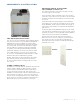
COMPONENTS & INSTALLATION
Preliminary specifications. Subject to change.
RAVRG2 RAVRG4