
Architect and Engineering Manual


27
PREPARATION OF THE WALL SLEEVE FOR ALL
TYPES OF CONSTRUCTION
Do not remove the stiffener from inside the wall sleeve or
the weather closure panel from the outside face of the wall
sleeve until the outdoor grille and chassis are ready to be
installed.
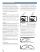
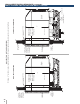
1. Position the wall sleeve into the wall. The room-side edge
of the RAB71B or RAB78B wall sleeve should be at least
flush with the finished wall for line-cord installations and
permanent-connection installations when no sub-base
is used, and should project into the room at least 2-3/8"
when a sub-base is used. The outside edge of the wall
sleeve should extend at least 1/4" beyond the outside wall.
This is necessary for proper caulking, to prevent sealing
the drain holes in the rear flange of the wall sleeve, and
to facilitate the installation of an accessory drain, if used.
If the minimum exterior dimensions are not met, refer to
pages 32–33.
The wall sleeve should be level from side to side and
from level to 1/4 bubble tilt to the outdoors. The
condensate disposal system in the unit is designed
to dissipate the condensate water generated during
cooling operation in accordance with AHRI standards
and actually uses this water for maximum unit
efficiency. A level unit will also ensure proper
drainage from the RAD10 drain kit to a building
internal drain and proper performance of the Internal
Condensate Removal (ICR) system optional on heat
pump units.
2. The wall sleeve should be secured to the wall at both
sides. Use a minimum of two screws or other fastening
device on each side. (See Figure 2 on page 28.) Mark the
wall sleeve on each side 2" from the bottom and 2" from
the top at a point where basic wall structure is located.
Drill wall sleeve and use fasteners appropriate for wall
construction. All holes for fasteners in the side of the
wall sleeve must be at least 2" up from the bottom of the
wall sleeve. Never locate screws or put other holes in the
bottom of the wall sleeve. The only exception is when an
RAD10 drain kit is installed to connect to an internal drain
system. (See page 37 for RAD10 drain kit information.)
If the wall opening is greater than the sleeve dimensions,
spacers must be used on the sides between the wall
sleeve and the wall support structure to prevent
distorting the wall sleeve.
3. Caulk or gasket the entire opening on the outside
between the wall sleeve and exterior wall surface (four
sides) to provide total water and air seal.
4. Caulk or gasket room-side opening between wall sleeve
and interior wall surface (four sides). Openings beneath
or around the wall sleeve can allow outdoor air to leak
into the room, resulting in increased operating costs and
improper room temperature control.
Care should be taken in location of electrical supply
entry in relationship to wall sleeve to assure access
to receptacle or junction box once unit is installed.
• Refer to page 45 for maximum power cord length.
• Permanently connected units close to finished floor
must allow for conduit clearance.
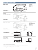
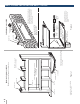
SLEEVE ANGLES
In some installations, such as curtain walls, window walls,
or where the structural material of the wall is insufficient
to support or fasten wall sleeve, sleeve angles may be
used. Sleeve angles are pieces of steel or other material of
similar structural strength that are formed to a 90° angle,
with holes to fasten the sleeve angle to the wall sleeve
and to the structural component of the wall surrounding
the wall sleeve.
The following describes the procedure when field-
fabricated and -installed sleeve angles are applied.
1. Position sleeve angles around top and sides of wall
sleeve at the desired location. Position sleeve angles
vertically on each side of wall sleeve to provide a level
installation.
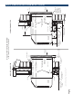
2. Mark wall sleeve through holes in sleeve angles. The
lowest hole on the sides of the wall sleeve must be a
minimum of 2" above the bottom of the sleeve.
3. For RAB71B wall sleeve, drill 5/32" diameter holes
at locations marked on wall sleeve in Step 2, and
assemble angles to wall sleeve using #10 x 1/2" self-
tapping screws. For RAB78B wall sleeve, follow the
same procedure except use a #10 x 1/2" bolt, washer
and nut to attach sleeve angles to sleeve. Install screws
or bolts from inside
wall sleeve.
4. Do not drill any holes in bottom of wall sleeve.
Do not distort wall sleeve.
5. Do not use sleeve angles for a lintel.
WALL SLEEVE INSTALLATION DATA (CONTINUED)
ARCHITECTS & ENGINEERS DATA MANUAL AZ45/AZ65 SERIES