
Architect and Engineering Manual


25
of 250 volts be “permanently connected.” There are also
some installations where units connected to voltage
sources under 250 volts may also need to be “permanently
connected.” If you are in doubt about the requirements
for a particular installation, consult Article 440 of the NEC
or the local electrical inspector. These requirements are
designed to protect personal safety and should be strictly
followed. Although NEC is cited here as a reference, all
electrical wiring and installations must conform to any
and all local electrical codes and regulations.
“Permanent connection” generally means wiring to the
unit must be contained in an enclosed “chaseway,” where
access to the wiring connections is more restrictive
than a normal line cord plugged into a receptacle. NEC
requirements may be met by using flexible or rigid conduit
to contain the wiring between the unit and a junction
box that contains the wiring connections. The conduit
is connected to the unit and to the junction box with
connectors to hold the conduit in place. The junction
box may be located in the floor or the wall of the structure,
but only approved connectors may be used outside the
unit or the junction box. The sub-base is UL
®
listed as a
junction box for permanent connection of a Zoneline unit.
Using a sub-base in an installation requiring permanent
connection provides a convenient, consistent location
for unit wiring to be connected to building wiring. The use
of a sub-base is not required, but the convenience and the
improved aesthetics it offers make the use of a sub-base
a viable means of permanent connection.
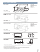
RAK204U — The RAK204U Series of sub-base provides
a design that fits the site needs and is available for use
with Zoneline PTAC/PTHP units. The RAK204U will most
likely be used for support of the wall sleeve and unit. The
RAK204U is the same physically as the other sub-bases
except there is no receptacle installed. Receptacles and
wiring can be field installed and, by using the RAK205CW
chaseway and the RAK4002D junction box, perform
the same function as any of the other sub-base kits by
selecting the correct receptacle and installing it in the
interior mounting plate inside the RAK204U.
230/208-volt receptacles can also be mounted in the
cover plate for easy access when direct-connect wiring
is not required. 265-volt units are to be “Permanently
(or Direct) Connected” and the external receptacle
(when wiring is not enclosed in a chaseway) does not
meet this requirement. A knockout for a fuseholder
or a disconnect is also provided in the cover plate.
The 230/208-volt sub-bases include a short, sub-base
power connection kit. Since sub-base connected units
are not considered to be line-cord connected, a Leakage
Current Detection Interrupter or Arc Fault Current
Interrupter device is not necessary.
RAK204D15C 208/230-volt 15-amp receptacle. Receptacle
is NEMA6-20R with 18" of #12AWG wires attached to the
receptacle. Short power connection kit included. Chaseway
included.
RAK204D20C 208/230-volt 20-amp receptacle.
Receptacle is NEMA6-20R with 18" of #12AWG wires
attached to the receptacle. Short power connection kit
included. Chaseway included.
RAK204D30C 208/230 volt 30-amp receptacle.
Receptacle is NEMA6-30R with 18" of #12AWG wires
attached to the receptacle. Short power connection kit
included. Chaseway included.
The junction box (RAK4002D for AZ45 and AZ65
Series units) that mounts on the chassis of 230/208-
volt sub-base connected units must be purchased
separately.
SUB-BASES FOR THE 265-VOLT UNITS:
RAK204E15C 265-volt 15-amp receptacle.
Receptacle is NEMA7-15R with 18" of #12AWG wires
attached to the receptacle. Chaseway and 3’ Power
Connection Kit included.
RAK204E20C 265-volt 20-amp receptacle.
Receptacle is NEMA7-20R with 18" of #12AWG wires
attached to the receptacle. Chaseway and 3’ Power
Connection Kit included.
RAK204E30C 265-volt 30-amp receptacle.
Receptacle is NEMA7-30R with 18" of #12AWG wires
attached to the receptacle. Chaseway and 3’ Power
Connection Kit included.
The junction box for 265-volt units is shipped with the
chassis since all 265-volt units are to be “permanently
(or direct) connected.”
There are separate internal compartments to permit
separation of low-voltage (Class 2) connections from
line-voltage connections as required by National Electrical
Code (NEC). Conduit containing building wiring enters
the sub-base through knockouts located in the rear or
bottom of the sub-base and is not accessible when the
wall sleeve is installed.
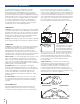
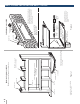
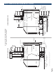
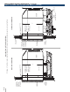
The sub-base attaches to the RAB71B wall sleeve with
two clips (field-assembled) that are screwed into field-
drilled holes in the bottom front flange of the wall sleeve.
It attaches to the RAB78B wall sleeve with clips that fit
over molded ribs without requiring the use of screws into
the wall sleeve. (See page 35 for illustration.) Since the
sub-base extends under the wall sleeve, clearance from
the inner edge of the wall sleeve to the finished wall must
be 2-3/8" or greater. The sub-base has four leveling legs
and adjustable side channels to enable the area under the
wall sleeve to be enclosed. Clearance from the bottom
edge of the wall sleeve to the finished floor must be
between 3" and 5".
The sub-base may be used as support for the chassis and
wall sleeve in installations where the wall is of insufficient
thickness to provide secure mounting of the wall sleeve.
WALL SLEEVE INSTALLATION DATA (CONTINUED)
ARCHITECTS & ENGINEERS DATA MANUAL AZ45/AZ65 SERIES