
Architect and Engineering Manual


24
A choice of wall sleeves is available for Zoneline
®
units.
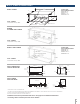
RAB71B — This insulated sleeve is constructed of heavy-
gauge galvanized steel and finished with a baked-enamel
finish for protection and appearance. Design of the sleeve
provides for support of the chassis and free draining of any
water entering the wall sleeve. A petroleum microcrystalline
wax is applied at critical points of fabrication to seal against
moisture. The dimensions of the RAB71B wall sleeve are
42" wide by 16" high by 13-3/4" deep, the same dimensions
as the original wall sleeve for GE Zoneline units built in
1961. The RAB71B wall sleeve is also available in depths
other than the standard depth. It is available on special
order as: RAB7116B – 16" deep; RAB7118 – 18” deep;
RAB7120 – 20” deep; RAB7124B – 24" deep.
All these special-order deep wall sleeves are insulated
and have sheet-metal dividers, or splitters, to prevent
the recirculation of condenser discharge air.
RAB81 — Heavy gauge steel wall sleeve with insulated top
and sides in a 4 piece “Quick Snap” universal design. This
easy to assembly product is shipped in an easy to handle
box making it better for shipping and better for the job
site. Can also be ordered and shipped preassembled as
the RAB81B.
RAB78B — This non-insulated wall sleeve is four molded
Quick Snap pieces made of fiberglass-reinforced polyester
compound and stainless steel latches. This sheet-molded
compound (SMC) wall sleeve offers outstanding strength,
durability, color retention, water integrity and corrosion
resistance. The dimensions of the RAB78B wall sleeve are
42" wide by 16" high by 14" deep.
• Wall sleeves are of universal design, accepting all
Zoneline chassis of current design as well as all
GE Appliances Zoneline chassis produced since 1961.
• Drain holes are provided in the rear of all wall sleeves to
permit excessive cooling condensate water, heat pump
condensate or precipitation entering the wall sleeve to
drain freely. A drain kit may be connected to the wall
sleeve to control any water draining from the wall sleeve.
See pages 37–38 for information on RAD10 Drain Kit.
WALL SLEEVE INSTALLATION DATA
GENERAL
Generally, Zoneline
®
units are installed 3" to 5" above the
floor (flush to finished floor installation is possible) as
near to the center of the room as possible; underneath
a window or a glass panel is typical. Normal installation
of the wall sleeve allows installation flexibility; from flush
with the finished interior wall to a minimum of 1/4" of
the wall sleeve extending beyond the finished exterior
of the building. Special consideration must be given
to installations where the wall sleeve does not extend
a minimum of 1/4" beyond the finished exterior wall.
See pages 32–33 for information on this type of
installation. The unit may be installed high in the
wall and these installations usually require a remote
thermostat (discussed on pages 17-19).
Regardless of the installation, there are several things to
consider when selecting a location for installing the unit.
For instance, drapery location could interfere with air
discharge, and placement of furniture may have an impact
on the performance of the unit. The following information
is intended to minimize installation problems and assure
you of trouble-free installation.
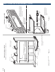
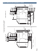
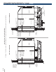
Refer to page 28 for required wall opening dimensions.
Minimum recommended interior and exterior sleeve
projections for standard wall thicknesses are shown in
the drawings in this manual. The sleeve may be installed
flush with the finished indoor wall. Special attention
must be paid to room-side sleeve projection when the
unit is installed in a ducted application as shown on
pages 40–41.
In walls thicker than 13-1/2" for line-cord-connected units
and 11-1/8" for sub-base installations, it may be necessary
to install a field-fabricated sleeve extension or use one
of the special-order RAB71 deep wall sleeves. Such
extensions must be carefully flashed and sealed both to
the wall sleeve and to the wall to ensure water integrity.
This is necessary to ensure that any water entering the
wall sleeve, either from operation of the unit or from
other sources, such as rain storms or from washing the
exterior of the building, will drain from the sleeve without
the possibility of capillary action drawing the water into
either the room or the wall cavity. In an installation where
the sleeve is recessed less than 3" from the outside
surface, flashing and sealing may be all the modification
necessary. In such an installation, the sides and top of the
wall opening must be waterproof to prevent moisture from
seeping into and damaging the walls. See pages 32–33
for suggested detail. Since the installation of a sleeve
extension requires a considerable amount of attention,
we recommend using one of the deep wall sleeves if the
standard sleeve is not of sufficient depth.
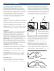
Mounting an outdoor grille or louver section to the
building face may cause a space between the outdoor
coil and the louver section. Air splitters, aligned with the
ends of the outdoor coil, must be installed between the
outdoor coil inlet and outlet air streams. Gaps between
the outdoor coil and the louver section may allow
condenser air recirculation and affect the operation of
the unit. See page 43 for requirements for custom louvers.
The wall sleeve should be level from side to side and
from level to 1/4 bubble tilt to the outdoors. The
condensate disposal system in the unit is designed
to dissipate the condensate water generated during
cooling operation in accordance with AHRI standards
and actually uses this water for maximum unit
efficiency. A level unit will also ensure proper drainage
from the RAD10 drain kit to a building internal drain
and proper performance of the Internal Condensate
Removal (ICR) system optional on heat pump units.
SUB-BASE
The sub-base is an optional accessory for the Zoneline
unit. It is discussed with the wall sleeve information
since deciding whether or not to use a sub-base in
the installation is a factor in the location of the wall
opening. National Electrical Code
®
(NEC) requires that
air conditioning units connected to voltages in excess
WALL SLEEVE
ARCHITECTS & ENGINEERS DATA MANUAL AZ45/AZ65 SERIES