
Architect and Engineering Manual
17
In many installations, control of the operation of the unit
at a location remote from the unit itself is desired. A unit
mounted high in the wall or over a door, for instance,
where the unit-mounted controls are inaccessible, can
be connected to a wall-mounted thermostat. Other
installations may use remote thermostat control for design
or performance enhancement. The unit is connected to
the thermostat by low-voltage wiring which permits the
operation of the unit to be selected and the temperature
sensed at the thermostat.
Important Notes: Remote thermostat wiring should
not be run through the wall sleeve. Thermostat wiring
should exit the wall below the unit and enter the unit
between room cabinet and chassis. Wire molding may
be used to hide thermostat wiring. If a sub-base is
used, the thermostat wiring may be concealed by the
sub-base. Thermostat wiring should not be run parallel
to line voltage wires since induced current may cause
erratic operation.
All Zoneline
®
AZ45 and AZ65 Series units are adaptable to
Class 2 remote low-voltage thermostats. The only additional
field-supplied components are the remote thermostat and
wiring necessary to connect it.
The controls on the unit are not functional when the remote
control function is used.
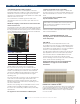
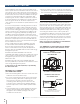
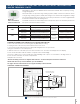
CONTROL PANEL
USE WALL THERMOSTAT
—will illuminate whenever any
button on the unit controls is
pressed if the unit is set up to
be controlled by a remote wall
thermostat. The LED will dim
down after a few seconds and
then turn off after a few minutes as to not disturb the guest
in a dark room.
RESISTANCE HEAT MODELS
The Zoneline AZ45 series resistance heat units may be
connected to a single-stage thermostat designed for use
with cooling with electric heat systems. GE Appliances
offers four thermostats compatible with the
AZ45 Series unit.
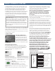
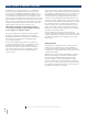
RAK149P2*
Digital programmable thermostat
with one fan speed works with
single-stage or two-stage heating
systems. Requires five connection
wires for AZ45 series.
RAK180W1*
Energy management occupancy sensing
wireless thermostat.
Note: Set Aux mode 6 to “A” mode for
Autochangeover thermostat. See page 15.
*NOTE: Default setup of unit is as a two-stage heating system and
must be changed to single stage for use with the AZ45 series.
RAK149F2*
Digital thermostat with two
fan speeds that works with
single-stage or two-stage heating
systems. Requires six connection
wires for AZ45 series.
The remote thermostat-Class 2 option (Mode 6 in the
auxiliary control setting) must be turned ON to enable
remote thermostat control. Refer to installation
instructions packaged with the chassis.
Please see page 51 for installation recommendations
for the remote thermostat wiring. Compatibility
of other thermostats considered for use with GE
Appliances Zoneline units is the responsibility of
the customer.
The control voltage on the remote control conductors is
24-volts AC. The AC voltage may not be compatible with
some solid-state thermostats.
If using a 1-fan speed remote thermostat, the fan speed
for the AZ45 Series in remote thermostat operation
is selected by the connection of the fan wire from the
thermostat to either the HIGH or LOW wire on the remote
thermostat connector. See the sketch of the connector
below for the color of the HIGH and LOW fan-speed wire.
Operating the unit in low fan speed reduces the operating
sound level of the unit and increases dehumidification of
the room.
Freeze Sentinel and Heat Sentinel remain operational if
the unit is connected to a remote thermostat. The unit
may be connected to a Central Desk Control (CDC)
system and controlled with a remote thermostat when
the CDC system has the unit in operation. See page 16
for additional information on the CDC system.
Unit temperature-limiting settings are not functional
when unit is connected to a remote thermostat.
NOTE: The low voltage transformer which powers
the remote thermostat (and other controls) is
“self-recovering” from potential wiring shorts. Should
you lose low voltage control power (to the thermostat
and the display panel on the unit), remove power to
the unit, check the thermostat wiring for shorts,
correct the issue and reapply power to the unit.
NOTE: With the new AZ45 and AZ65 Series,
thermostat twinning is allowed, where more than
one unit may be connected to a single remote
thermostat. In order to accomplish this, ONLY ONE
POWER SOURCE (24VAC – R TERMINAL WIRE) CAN
BE CONNECTED TO THE THERMOSTAT. All other
thermostat wires of the additional unit should be
connected as directed.
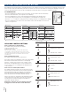
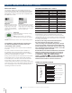
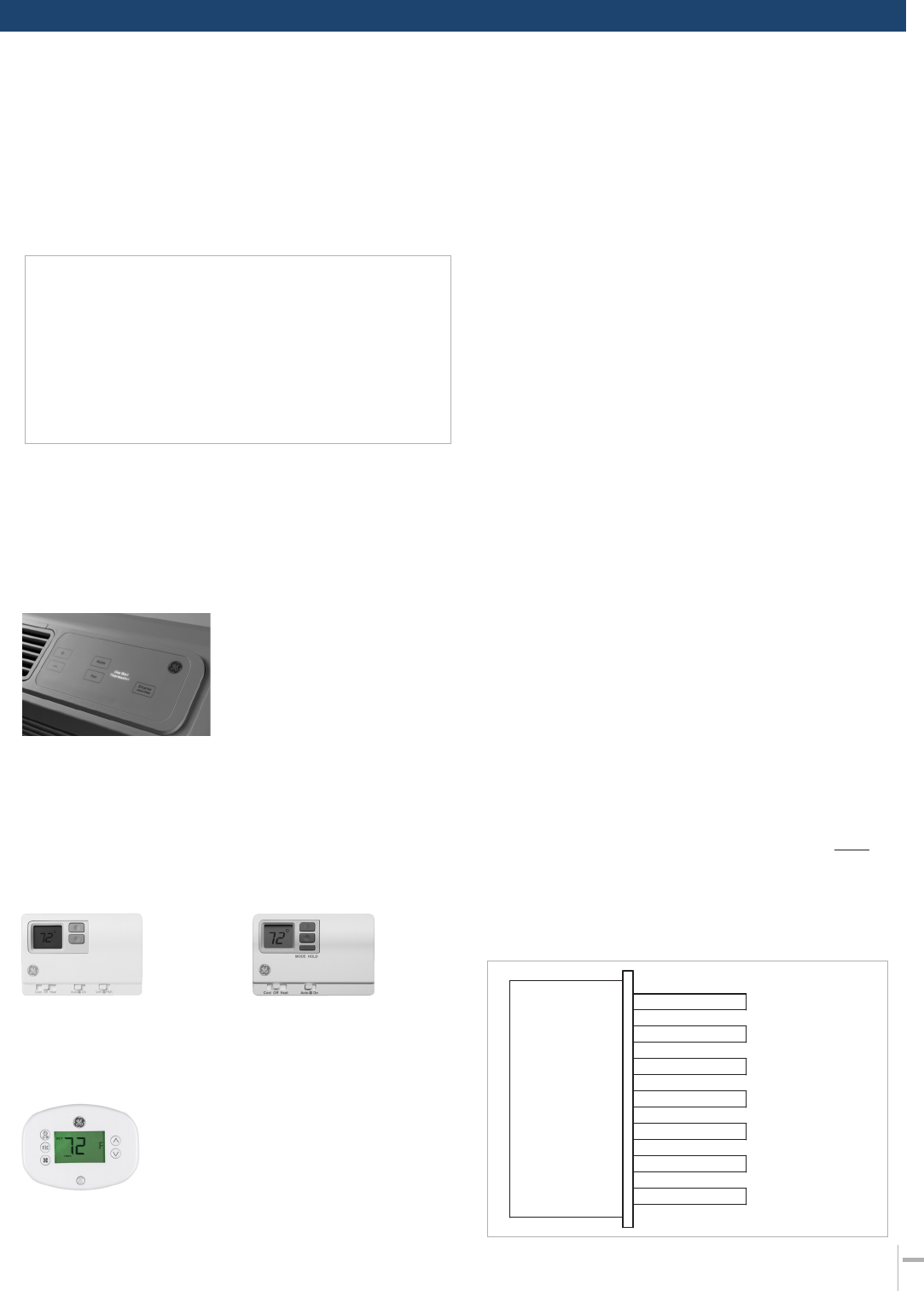
THERMOSTAT WIRING DIAGRAM
Black -C- Common
White -W- AUXHeat
Yellow -Y-Compressor
Blue -not used
on AZ45 Series
Green -GH- HighFan
Tan -GL- LowFan
Red -R- 24VAC
Zoneline Thermostat
Connector
REMOTE THERMOSTAT CONTROL