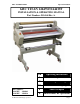
GBC 1264WF/1244WF Operation Manual GBC TITAN 1264WF/1244WF INSTALLATION & OPERATING MANUAL Part Number: 930-144 Rev A.
GBC 1264WF/1244WF Operation Manual GB The information in this publication is provided for reference and is believed to be accurate and complete. General Binding Corporation (GBC) is not liable for errors in this publication or for incidental or consequential damage in connection with the furnishing or use of the information in this publication, including, but not limited to, any implied warranty of fitness or merchantability for any particular use.
GBC 1264WF/1244WF Operation Manual TABLE OF CONTENTS Description Cover Legal Disclaimer Table of Contents Important Safety Instructions Important Safeguards General ,Electric & Service Warranty Specifications Pre- Installation Installation Page No. 1 2 3 4 4 5 5 6 6 Description Top/Bottom Temperature Control Stop Reverse Auto-Off Ready Wait Page No.
GBC 1264WF/1244WF Operation Manual IMPORTANT SAFETY INSTRUCTIONS YOUR SAFETY AS WELL AS THE SAFETY OF OTHERS IS IMPORTANT TO GBC. IN THIS INSTRUCTION MANUAL AND ON THE PRODUCT, YOU WILL FIND IMPORTANT SAFETY MESSAGES REGARDING THE PRODUCT. READ THESE MESSAGES CAREFULLY. READ ALL OF THE INSTRUCTIONS AND SAVE THESE INSTRUCTIONS FOR LATER USE. THE SAFETY ALERT SYMBOL PRECEDES EACH SAFETY MESSAGE IN THIS INSTRUCTION MANUAL. THE SYMBOL INDICATES A POTENTIAL PERSONAL SAFETY HAZARD TO YOU OR OTHERS.
GBC 1264WF/1244WF WARRANTY Limited 90- Day Warranty GBC warrants to the original purchaser for a period of ninety days on labor and one year on parts after installation that this laminator is free from defects in workmanship and material under normal use and service. GBC’s obligation under this limited warranty is limited to replacement or repair, at GBC’s option, of any part found defective by GBC without charge for material or labor.
GBC 1264WF/1244WF Operation Manual PRE-INSTALLATION Before a 1264WF/1244WF Laminator can be installed, ensure the following requirements are met: 1. 2. 3. Are doorways and hallways wide enough for the laminator to be moved to the installation site? Is there ample room for the laminator? A work area must be established that allows for operation in both the front and rear of the laminator and provides space for efficient material flow.
GBC 1264WF/1244WF Operation Manual Section 1: Detailed Specifications Specifications provide all of the technical data for the Titan 1244WF &1264WF Description: A high speed laminator for the graphic arts professional as well as for the manufacturer who produces promotional pieces in-house. A new elegant design, low power consumption and first class safety and quality assurances.
GBC 1264WF/1244WF Operation Manual Section 2: Consumables Film Types: Film Diameters: Poly-in films, thermal and PSA films Poly-out films, thermal and PSA Accushield Up to a 7 in. outside roll diameter. (18 cm.) 3 in. core standard. (76 cm.) Core Size: Film widths: 1264WF 61 in. Thermal films (155 cm.) 62 in. PSA (157 cm.) 12444WF 42 in. maximum paper width (107 cm.) 42 in. PSA films (107 cm.) Paper widths: 1264WF 62 in. Maximum paper width (157 cm.) 12444WF 42 in.
GBC 1264WF/1244WF Operation Manual Section 3: Function Speed: 0-10 fpm (0-6.1mpm) Motor: DC Geared Motor Heating Capabilities: Up to 320* F. (160*C) Controls: Operations control panel Roll Design: High release silicone main rollers High release pull roll Section 4: Electrical Requirements: 1264 WF: 1264WF CE: 230 VAC, 60Hz, Single phase, 30Amps. 230 VAC, 50Hz. Single phase, 20Amps. 1244 WF: 1244WF CE: 230 VAC, 60Hz. Single phase, 20 Amps. 230 VAC, 50Hz.
GBC 1264WF/1244WF Operation Manual Heater Wattage: 1264 WF: 1264WF CE: 4500W / Heater 3300W / Heater 1244 WF: 1244WF CE: 3000 W / Heater Amperage draw: 1264 WF: Drive Motor=3.3 Amps. Fan Motor=0.5 Amps. Motors and Heater=25 Amps. 1264WF CE: Drive Motor=3.3 Amps. Fan Motor=0.5 Amps. Motors and Heater=13 Amps. 1244 WF: 1244WF CE: Drive Motor=3.3 Amps Fan Motor=0.
GBC 1264WF/1244WF Connectors for 1264 WF Operation Manual Connectors for 1244 WF NEMA 6-20 P NEMA 6-30 P NEMA 6-30 R © 2006 General Binding Corporation NEMA 6-20 R Page 11
GBC 1264WF/1244WF Operation Manual Section 5: Dimensions Weight: 1264 WF: 1264WF CE: Crated: 750 lbs. (340 kg.) Uncrated: 600 lbs. (272 kg.) 1244 WF: 1244WF CE: Crated: 350 lbs (159 kg.) Uncrated: 275 lbs (125 kg.) 1264 WF: 1264WF CE: Crated: 58 in.(H) x 87 in. (W) x 40 in. (D) 147 cm. (H) x 221 cm. (W) x 102 cm. (D) Uncrated: 49in(H) x 77.25 in.(W) x 25.5 in. (D) 124 cm. (H) x196 cm. (W) x65cm.
GBC 1264WF/1244WF Operation Manual Section 6: Know your Laminator This section is intended to aide the user in becoming more familiar with the 1244 WF & 1264 WF laminators. Refer back to this section if you have questions regarding references to certain parts of the laminator in this laminator. 1.) Safety Shield 9.) Rewind Clutch Adjustment Knob 2.) Control Panel 10.) Rewind Shaft & Rewind Tube 3.) Feed Table 11.) Rear Slitter 4.) Lower Film Shaft/Unwind Shaft 12.) Power Switch 5.
GBC 1264WF/1244WF © 2006 General Binding Corporation Operation Manual Page 14
GBC 1264WF/1244WF © 2006 General Binding Corporation Operation Manual Page 15
GBC 1264WF/1244WF Know your Laminator Continued1.) Safety Shield: The Safety Shield aids in preventing the operators fingers from becoming pinched or burned in the heat rollers of the laminator. With the Safety Shield raised or removed, the machine goes into the safety mode that prevents the run button on the control panel from starting the rollers to turn. The foot pedal must be used when the Safety Shield is raised or removed. 2.
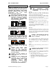
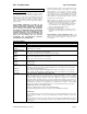
GBC 1264WF/1244WF Operation Manual Section 7: Display Control Panel Stand-by Pressing STAND-BY will cause the laminator to go into the AUTO-OFF mode. The laminator will automatically go into this mode after sitting idle for an extended amount of time. When in AUTO-OFF mode the laminator will no longer continue to heat the main rollers to save power. Stand-by Pressing MEMORY will cause the current speed and heat settings to be recorded in the JOB memory location shown on the display.
GBC 1264WF/1244WF Operation Manual Display Control Panel-Continued Top and Bottom Temperature Use the up or down arrow keys to increase or decrease the set temperature of the heat rollers. The temperature shown on the display is the temperature at which the unit is attempting to attain. For example if the unit is set to 200*F even though the actual roller temperature may be higher or lower. To view the actual temperature press MEASURE. Stop The STOP button ceases the forward rotation of the rollers.
GBC 1264WF/1244WF Operation Manual Display Control Panel-Continued The Temperature displayed in the area referred to as TOP TEMPERATURE and BOTTOM TEMPERATURE is the value that the laminator is attempting to attain. Pressing the MEASURE button will momentarily display the actual roller temperature. Fig. A The current speed and job settings are given on the right side of the display. The current state of the heat rollers is given on the lower portion of the display.
GBC 1264WF/1244WF Operation Manual Section 8: Safety The 1244Wf & 1264 WF have numerous safety features that will help keep the operator safe from harm. But for these features to work correctly, the user must become familiar with each of the safety mechanisms as well as never override a safety feature. Emergency Stop/E-Stop Two Emergency Stops (Sometimes referred to as E-Stops) are located on the 1244 WF & 1264 WF laminators. See the “Know your Laminator” section for the locations.
GBC 1264WF/1244WF Operation Manual Safety Shield-Continued To remove the Safety Shield, first raise the shield and locate the spring hinge pin on the right side of the shield. Pull the pin to release the shield from the laminator as illustrated in the photo. Feed Table The Feed Table supports the product to be laminated. It also prevents full access to the roller nip (where the upper and lower roller meet) of the laminator.
GBC 1264WF/1244WF Operation Manual Section 9: How to Guide This section discusses how to load film on the unwinds, how to center film, how to select and change the nip, how to center film, how to select and change the nip, how to use the inline slitters and rear slitter. Loading Film Begin by removing the hinge pin that prevents the film shaft from swinging outward. Swing the film shaft outward as is illustrated in the photo.
GBC 1264WF/1244WF Operation Manual Loading Film Continued The core chucks need to be adjusted to match the width of the film that is going to be loaded on the laminator. To do this, be gin by removing the rubber o-rings. Then use the included hex tool to loosen the setscrews in the core chucks. Note: Do not remove the setscrews; they only need to be loosened. Make the necessary adjustments to the upper roll of laminate to center it to the Main Rollers.
GBC 1264WF/1244WF Operation Manual Select and Change the Nip The Roller Handle raises and lowers the Main Rollers and Pull Rollers simultaneously. The Roller Handle Guide is notched with preset nip heights. The Roller Handle is located on the right side of the laminator. Keep hands and fingers clear of the laminator roller nip when changing the gap. You can be crushed or burned. Never leave the rollers in the down position without rotating. Prolonged contact in one area can form flat spots on the rollers.
GBC 1264WF/1244WF Operation Manual In-Line Slitters The In-Line Slitters allows the operator to slit the images as they pass through the Main Rollers and into the Pull Rollers. The trimmed waste can then be attached to the Rewinder Tubes and disposed of later. To engage the In-Line Slitters, simply press the lever down to expose the blade. Keep hands and fingers away from the path of the In-Line Slitters. The blade is extremely sharp and can cut you.
GBC 1264WF/1244WF Operation Manual Section 10: Applications The 1244 WF & 1264 WF can accommodate Poly-in or Poly-out films. Poly-out means the adhesive is on the outside of the roll. Each film requires a slightly different loading procedure. Refer to the Webbing diagrams at the end of this section. The shiny side of clear film must contact the heating components with the dull sides (adhesive side) facing out. Use caution when loading Matte or Delustered film since both sides appear dull.
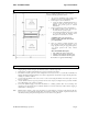
GBC 1264WF/1244WF Operation Manual Webbing Thermal Film Using Threading Card Fig.3 CAUTION: The laminator rollers will be hot and can burn you. For pressure sensitive film (PSA), refer to the section titled THERMAL LAMINATE WEBBING: USING FILM THREADING CARD FOR PSA FILM. 1. Turn the Main Power ON /OFF to On. 2. Set top and bottom temperature with regards to the film type used. 3. Ensure no brake tension is applied to the film shafts. 4.
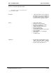
GBC 1264WF/1244WF Operation Manual Webbing PSA Film/Mount Adhesive Using Threading Card The laminator should be cool to the touch before Proceeding. Fig. 6 REWIND TUBE PSA Film Mount Adhesive Fig. 7 PSA Film 1. Turn the Power ON /OFF to On 2. Load the rolls of film as illustrated in (Fig. 6). Ensure no brake tension is applied to the film shafts. 3. Pull the top roll of film down under the idler bar and up to the upper front rewind tube. 4.
GBC 1264WF/1244WF Operation Manual Start Laminating 1. At this point you should have your laminator Webbed with the appropriate material for your application. 2. The feed table should be in the normal operating position. 3. Close the main and Pull roll nips. Rollers should be closed. 4. Speed is set to 3 or less and front motor direction is selected. 5. Press the start button. 6. Set main roller pressure at desired setting for laminating by turning the roll lift handle.
GBC 1264WF/1244WF Operation Manual Method for Tacking New Film to Existing Film The following describes a method for loading film whereby the existing film present on the heat rollers may be used in place of the threading card to draw the new film through the laminator. The adhesive of the existing film must be tacky or liquefied. Leading edges of the new film will be overlapped onto the tacky adhesive of the old film. The existing film and the new film will be pulled through the laminator together.
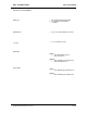
GBC 1264WF/1244WF Operation Manual To Unweb the laminator Unweb the laminator if you are changing film widths, cleaning the rollers or have finished using the machine for the day. (2) (1) CAUTION: Do not cut yourself 1. Using a slitter, cut (1) the output from the web (Fig. 13). 2. Cut (2) remaining top film web between the idler bar and heat roller. PSA film cut the release liner too. 3. Cut (3) the film web between the lower film supply and the idler bar (Fig. 13).
GBC 1264WF/1244WF Operation Manual Tips for Pre Coating Boards MOUNT ADHESIVE LEADER BOARD TRAILOR BOARD BOARDS Fig. 15 1. Load the laminator as illustrated in (Fig. 15). Remove chill idler. 2. The width of the roll should not exceed the width of the board by more than 1/2 in. (1.3 cm). 3. Use a leader board to set the main roller and pull roller pressure prior to webbing. 4. Use a leader board to start the run and a trailer board to finish the run. 5.
GBC 1264WF/1244WF Operation Manual Tips for Creating a Decal 1. Load the laminator as illustrated in Fig. 18. 2. The over laminate may be PSA or thermal type. 3. If using thermal type, pay attention to the Polyin/Poly-out rule. 4. Run a test material prior to running the actual image to ensure flat output. 5. Use minimal brake tension to achieve quality output. 6. Do not web the PSA mount adhesive around the lower web idler.
GBC 1264WF/1244WF Operation Manual Tips for ACCUSHIELD THERMAL FILM IMAGE OPTIONAL SEPERATOR BAR OUTPUT KRAFT PAPER OPTION 1. Load the laminator as illustrated in Fig.21. 2. You must have the Separator bar option to accurately run this material. See your Sales Rep for ordering the Separator Bar. 3. Set Top Temp to 265 o F* (129* C) and a speed setting no greater than 4. 4. Liner rewind tension will be greater than normal operating standard 5.
GBC 1264WF/1244WF Operation Manual SPEED / TEMPERATURE CONTROL This is only a general reference guide. Different settings may be suitable as the warm up time, lamination time and materials change. Factors that may affect the speed and temperature parameters; 1. 2. 3. 4. 5. 6. 7. 8. 9. Image length Image width and ink coverage. Ink coverage Paper type Laminate thickness Operating environment Condition of the rollers Line voltage (effects heaters) Using cooling features.
GBC 1264WF/1244WF Operation Manual Heat -A- -B- Fig. 24 The “READY” indicator may extinguish if the speed is set too fast for the material being laminated. Either lower the speed setting or press STOP and wait until the “READY” indicator illuminates. Operation of the laminator for more than thirty minutes at a time may necessitate a lower speed setting. It is recommended that, during periods of long runs, the items being laminated are alternated between thick and thin.
GBC 1264WF/1244WF Operation Manual MAINTENANCE Caring For the GBC 2064WF Laminator GBC offers Cleaning kits as well as Extended Maintenance Agreements. Contact your local GBC Service Representative or your dealer/distributor for additional information. The only maintenance required by the operator is to periodically clean the heat rollers and schedule semi annual maintenance checks.
GBC 1264WF/1244WF Operation Manual TROUBLE SHOOTING GUIDE SYMPTOM The control panel display does not illuminate when POWER ON/OFF is in the ON, marked “I”, position Heat rollers do not turn when I POSSIBLE CAUSE CORRECTIVE ACTION Laminator not connected to electrical supply Insert attachment plug into receptacle Blown out fuse. Feed table not properly installed. Check fuses. Tilt feed table and properly replace it. Pull out on the E-STOP push button. Disengage the footswitch mode. Clear nip area.
GBC 1264WF/1244WF © 2006 General Binding Corporation Operation Manual Page 39