GBC 3064WF Operation Manual GBC 3064WF INSTALLATION & OPERATING MANUAL Part Number: 930-131, Rev A. Part Number: 930-131.REV.
GBC 3064WF Operation Manual ENG The information in this publication is provided for reference and is believed to be accurate and complete. General Binding Corporation (GBC) is not liable for errors in this publication or for incidental or consequential damage in connection with the furnishing or use of the information in this publication, including, but not limited to, any implied warranty of fitness or merchantability for any particular use.
GBC 3064WF Operation Manual ENG TABLE OF CONTENTS Description Cover Legal Disclaimer Table of Contents Important Safety Instructions Important Safeguards General Electrical Service Warranty Specifications Pre- Installation Installation Control Guide Power ON/OFF Control Panel LCD Display Display Reset Switch Display Main Switch (TOP Heater) Display Main Switch (Bottom Heater) Fan Switch Main Roller (Up / Down) Pull Roller (Up / Down) Laminator main Control Switch Machine Power On Light Laminator Direction
GBC 3064WF Operation Manual IMPORTANT SAFETY INSTRUCTIONS YOUR SAFETY AS WELL AS THE SAFETY OF OTHERS IS IMPORTANT TO GBC. IN THIS INSTRUCTION MANUAL AND ON THE PRODUCT, YOU WILL FIND IMPORTANT SAFETY MESSAGES REGARDING THE PRODUCT. READ THESE MESSAGES CAREFULLY. READ ALL OF THE INSTRUCTIONS AND SAVE THESE INSTRUCTIONS FOR LATER USE. THE SAFETY ALERT SYMBOL PRECEDES EACH SAFETY MESSAGE IN THIS INSTRUCTION MANUAL. THE SYMBOL INDICATES A POTENTIAL PERSONAL SAFETY HAZARD TO YOU OR OTHERS.
GBC 3064WF Operation Manual WARRANTY Limited 90- Day Warranty GBC warrants to the original purchaser for a period of ninety days on labor and one year on parts after installation that this laminator is free from defects in workmanship and material under normal use and service. GBC’s obligation under this limited warranty is limited to replacement or repair, at GBC’s option, of any part found defective by GBC without charge for material or labor.
GBC 3064WF Operation Manual PRE-INSTALLATION Before a 3064 Laminator can be installed, ensure the following requirements are met: 1. 2. 3. Are doorways and hallways wide enough for the laminator to be moved to the installation site? Is there ample room for the laminator? • A work area must be established that allows for operation in both the front and rear of the laminator and provides space for efficient material flow.
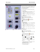
GBC 3064WF Operation Manual CONTROL GUIDE A. Power ON/OFF (I/O): Located at the back left of the machine applies power to the laminator. The control panel display will illuminate when position marked “I” is pushed. The Off position, marked “O” removes power from the laminator. B. Control Panel (Figure 5) 1. Main Roll Nip Pressure relevant pressure in percentage: 2 a 1 3 4 b 8 5 6 9 1 7 2.
GBC 3064WF Operation Manual FEATURES GUIDE Refer to the following pages for detailed information on the above Features FEATURES GUIDE (DETAILED DESCRIPTION) EMERGENCY STOP BUTTONS (Fig. 1– Item A) Four emergency stop buttons are available on the Laminator on the top four corners of the Laminator. To engage Emergency -stop button, Press any emergency -stop safety push button to stop the roller movement A To disengage, turn the push button clockwise after the emergency condition has been resolved.
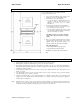
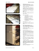
GBC 3064WF Operation Manual A B C Figure 2 B Media Tables: (Fig. 2C & 3C) On both the Front Media & Rear Media tables, the safety interlock switch will not allow the Laminator to operate at full speed unless the tables are properly installed. The Media tables are used to position items for Lamination. There are two media tables on the machine one on the front & one on the rear of the Laminator. The Front Media table incorporates an Idler on the leading edge of the table.
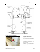
GBC 3064WF Operation Manual A Figure 5 Removable Chill Idler: (Fig. 6 – Item A) A The removable chill Idler is used to help smooth out the laminating film during the cooling process.
GBC 3064WF Operation Manual Upper Tension Idler: (Fig. 7 – Item A) A Upper tension Idler guides the laminating film on to the main roll insuring a consistent amount of wrap on the upper rolls. Figure 7 Lower Tension Idler: (Fig. 8 - Item B) B Lower tension idler guides the lower lamination film on to the lower roller. Figure 8 Pull Rollers: (Fig. 9 - Item A) A The Pull rollers located at the back of the laminator are motor driven.
GBC 3064WF Operation Manual Heated Main Rollers: (Fig. 10 – Item A) A B Silicone rubber coated steel tubes heat the laminating film and compresses the heated film to the items being laminated. Heat is provided by an internal heating element. Table Idler: (Fig. 10 – Item B) The Table Idler is used to assist in bringing the material up to the nip. The table Idler is helpful in roll to roll operation and helps move large ridged panels through the nip. Figure 10 Main On / Off (I/O) Switch: (Fig.
GBC 3064WF Operation Manual Nip Pressure Adjustment: (Fig. 14 & 15 –Item A) The Nip pressure adjustment allows the operator to adjust the downward pressure of the pull rolls and main rolls. A Pull Roll Lift handle: Turn the handle clockwise to lower the upper pull roll. (Fig. 14A) Figure 14 Heated Main roll Lift handle: Turn handle clockwise to lower main roll & adjust the Nip Pressure (Fig.
GBC 3064WF Operation Manual SEQUENCE OF OPERATIONS GBC U.S &CE 3064WF Effect of Fiber Optics on sequence of operation Modes Situation 1 Situation 2 Situation 3 Machine Run Mode Normal operation (No Interruption to any safety circuitry & Fiber optic beam)High speed. Interrupted fiber optic beam or opened any safety circuitry. Fiber optic beam cleared + all safety circuitries are closed Control panel: Forward Speed: Zero to Max.
GBC 3064WF Operation Manual OPERATING INSTRUCTIONS Film Loading & Threading The top and bottom rolls of laminating film must be of the same width and be present simultaneously. A Small amount of adhesive will “squeeze out” during Lamination. Hardened adhesive deposits can damage the heat rollers. CAUTION: Adhesive will deposit on the rollers if: • Only one roll is used. n ly-i Po • Different widths of rolls are loaded together.
GBC 3064WF Operation Manual Webbing Thermal Film Using Threading Card THERMAL LAMINATE CAUTION: The laminator rollers will be hot and can burn you. 1. Turn the Main Power ON /OFF to On. 2. Set top and bottom temperatures to the appropriate setting for the film type used. 3. Ensure no brake tension is applied to the film shafts. 4. Pull the top roll film down under the upper idler bar and allow to drape over the top heat roller (Fig. 19) 5.
GBC 3064WF Operation Manual REWIND TUBE Webbing PSA Film/Mount Threading Card Adhesive Using PSA Film The laminator should be cool to the touch before Proceeding. Mount Adhesive Figure 22 REWIND TUBE PSA Film Mount Adhesive Figure 23 REWIND TUBE PSA Film CHILLED ROLLER 1. Turn the Power ON /OFF to On 2. Load the rolls of film as illustrated in (Fig. 22). Ensure no brake tension is applied to the film shafts. 3.
GBC 3064WF Operation Manual Start Laminating 1. At this point you should have your laminator Webbed with the appropriate material for your application. 2. The feed table should be in the normal operating position. 3. Close the main and Pull roll nips. Rollers should be closed. 4. Speed is set to 3 or less and “FRONT” ( ) motor direction is selected. 5. Press the “START” ( ) button. 6. Set main roller pressure between 40% – 60% for laminating by turning the main roll lift handle.
GBC 3064WF Operation Manual Method for Tacking New Film to Existing Film (1) The following describes a method for loading film whereby the existing film present on the heat rollers may be used in place of the threading card to draw the new film through the laminator. The adhesive of the existing film must be tacky or liquefied. Leading edges of the new film will be overlapped onto the tacky adhesive of the old film. The existing film and the new film will be pulled through the laminator together.
GBC 3064WF Operation Manual To unweb the laminator Unweb the laminator if you are changing film widths, cleaning the rollers or have finished using the machine for the day. (2) (1) CAUTION: Do not cut yourself (3) 1. Using the rear slitter, cut (1) the output from the web (Fig. 28). 2. Cut (2) remaining top film web between the idler bar and heat roller. PSA film cut the release liner too. 3. Cut (3) the film web between the lower film supply and the idler bar (Fig. 28). (2) .......
GBC 3064WF Operation Manual APPLICATIONS Tips for Pre Coating Boards MOUNT ADHESIVE LEADER BOARD TRAILOR BOARD BOARDS Figure 30 1. Load the laminator as illustrated in (Fig. 30). Remove chill idler. 2. The width of the roll should not exceed the width of the board by more than 1/2 in. (1.3 cm). 3. Use a leader board to set the main roller and pull roller pressure prior to webbing. 4. Use a leader board to start the run and a trailer board to finish the run. 5.
GBC 3064WF Operation Manual Tips for Creating a Decal 1. Load the laminator as illustrated in Fig. 33. 2. The over laminate may be PSA or thermal type. 3. If using thermal type, pay attention to the Polyin/Poly-out rule. 4. Run a test material prior to running the actual image to ensure flat output. 5. Use minimal brake tension to achieve quality output. 6. Do not web the PSA mount adhesive around the lower web idler.
GBC 3064WF Operation Manual REWIND THERMAL FILM Tips for ACCUSHIELD IMAGE OPTIONAL SEPERATOR BAR OUTPUT ROLL TO ROLL OPTION 1. Load the laminator as illustrated in Fig. 36. 2. You must have the Separator bar option to accurately run this material. 3. Set Top Temp to 265oF (129oC) and a speed setting no greater than 4. 4. Liner rewind tension will be greater than normal operating standard 5. To prevent some adhesive adhering to the rollers, you may choose to use a roll of craft paper for a Carrier.
GBC 3064WF Operation Manual SPEED / TEMPERATURE CONTROL This is only a general reference guide. Different settings may be suitable as the warm up time, lamination time and materials change. Factors that may affect the speed and temperature parameters; 1. 2. 3. 4. 5. 6. 7. 8. 9. Image length Image width and ink coverage. Ink coverage Paper type Laminate thickness Operating environment Condition of the rollers Line voltage (effects heaters) Using cooling features.
GBC 3064WF Operation Manual Heat -A- -B- Figure 39 The “READY” indicator may extinguish if the speed is set too fast for the material being laminated. Either lower the speed setting or press “STOP” ( ) and wait until the “READY” indicator illuminates. Operation of the laminator for more than thirty minutes at a time may necessitate a lower speed setting. It is recommended that, during periods of long runs, the items being laminated are alternated between thick and thin.
GBC 3064WF Operation Manual MAINTENANCE Caring For The GBC 3064WF Laminator GBC offers Cleaning kits as well as Extended Maintenance Agreements. Contact your local GBC Service Representative or your dealer/distributor for additional information. The only maintenance required by the operator is to periodically clean the heat rollers and schedule semi annual maintenance checks.
GBC 3064WF Operation Manual TROUBLE SHOOTING GUIDE SYMPTOM POSSIBLE CAUSE The control panel display does not illuminate when POWER ON/OFF is in the ON, marked “I”, position. Heat rollers do not turn when POWER ON/OFF is in the ON, marked “I”, position. Press the “RUN” ( ) button and the motor does not turn. Heat rollers only turn if I use the “Footswitch”. Laminated items exhibit curling. Laminator not connected to electrical supply Blown out fuse. Feed table not properly installed.