GBC 2064WF-1 Operation Manual GBC 2064WF-1 INSTALLATION & OPERATING MANUAL Part Number: TBD, Rev A. Part Number: ???-??? GB Operating Instructions I Istruzioni per l'Uso D Bedienungsanleitungen NL Gebruiksaanwijzing F Mode d'Emploi E Instrucciones de Operación © 2009 General Binding Corporation an ACCO Brands CO.
GBC 2064WF-1 Operation Manual GB The information in this publication is provided for reference and is believed to be accurate and complete. General Binding Corporation (GBC) is not liable for errors in this publication or for incidental or consequential damage in connection with the furnishing or use of the information in this publication, including, but not limited to, any implied warranty of fitness or merchantability for any particular use.
GBC 2064WF-1 Operation Manual TABLE OF CONTENTS Description Cover Legal Disclaimer Table of Contents Important Safety Instructions Important Safeguards Page No.
GBC 2064WF-1 Operation Manual IMPORTANT SAFETY INSTRUCTIONS YOUR SAFETY AS WELL AS THE SAFETY OF OTHERS IS IMPORTANT TO GBC. IN THIS INSTRUCTION MANUAL AND ON THE PRODUCT, YOU WILL FIND IMPORTANT SAFETY MESSAGES REGARDING THE PRODUCT. READ THESE MESSAGES CAREFULLY. READ ALL OF THE INSTRUCTIONS AND SAVE THESE INSTRUCTIONS FOR LATER USE. THE SAFETY ALERT SYMBOL PRECEDES EACH SAFETY MESSAGE IN THIS INSTRUCTION MANUAL. THE SYMBOL INDICATES A POTENTIAL PERSONAL SAFETY HAZARD TO YOU OR OTHERS.
GBC 2064WF-1 Operation Manual WARRANTY Limited 90- Day Warranty GBC warrants to the original purchaser for a period of ninety days on labor and one year on parts after installation that this laminator is free from defects in workmanship and material under normal use and service. GBC’s obligation under this limited warranty is limited to replacement or repair, at GBC’s option, of any part found defective by GBC without charge for material or labor.
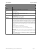
GBC 2064WF-1 Operation Manual SPECIFICATIONS Operating Speed Maximum Temperature Maximum Mounting Thickness Maximum Film Width Dimensions (W x D x H) Weight Electrical Requirements US ModelsCE ModelsFCC NOTE Up to 18 fpm (5.5 mpm) MAX 300°F (149°C) Main Roller-1 in. (25.4 mm) Max. Pull Roller-1/2 in. (12.5mm) Working gap. 1 in. total opening gap. 64 in. (162.5 cm) Unit alone: (Uncrated) 82.5in x 41in x 54in (209cm x 104cm x 137cm) Depth of 2064WF-1 is 44in (112 cm) with tables in up position.
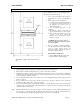
GBC 2064WF-1 Operation Manual PRE-INSTALLATION Before a 2064WF-1 Laminator can be installed, ensure the following requirements are met: 1. 2. 3. Are doorways and hallways wide enough for the laminator to be moved to the installation site? Is there ample room for the laminator? • A work area must be established that allows for operation in both the front and rear of the laminator and provides space for efficient material flow.
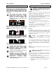
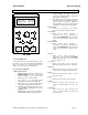
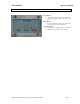
GBC 2064WF-1 Operation Manual CONTROL GUIDE • 1 Set Temp. Current Temp. TOP: 140*F TOP: 150*F BOT: 150*F TOP: 145*F GAP: 000% MODE: FWRD SPEED: 08ft PRS: 030% 3 8 2 Top Temp 4 Reset 7 MASTER DIAL Bottom Temp Meas. 5 6 Speed Cooling 9 10 11 Stop Rear Forward FIGURE 1 A. Power ON/OFF (I/O): Located at the back left of the machine applies power to the laminator. The control panel display will illuminate when position marked “I” is pushed.
GBC 2064WF-1 Operation Manual REAR CONTROL A. Stop Button: • While running the machine from the Rear, by pressing the “STOP” button, the rollers will stop. B. Rear Button: • By pressing the “Rear” button, the machine will work going to the rear of the machine. C. Forward Button: • By pressing the “Forward” button, the machine will work going to the front of the machine. © 2009 General Binding Corporation an ACCO Brands CO.
GBC 2064WF-1 Operation Manual FEATURES GUIDE Refer to the following pages for detailed information on the above Features FEATURES GUIDE (DETAILED DESCRIPTION) EMERGENCY STOP BUTTONS: (Fig. 1– Item A) FIGURE 1 Four Emergency Stops buttons are available on the Laminator on the top four corners of the Laminator.
GBC 2064WF-1 Operation Manual FIGURE 4 Rear Media Table: The Rear Media Table (Fig.4A) is used to position items for Lamination. There are two media tables on the machine one on the front & one on the rear of the Laminator. Table Safety Interlock Switch: The Table Safety Interlock Switch (Fig.4B) ensures that the table is properly placed and secure. The Safety Interlock Switch will not allow the Laminator to operate at full speed unless the tables are properly installed.
GBC 2064WF-1 Operation Manual FIGURE 8 Lower Tension Idler: (Fig.8A&9A) The Lower Tension Idler Guides the lower lamination onto the Bottom Main Roller insuring a constant amount of wrap on the Bottom Main Roller. Unwind Brake Tensioner: The Unwind Brake Tensioner (Fig.8B) is used to adjust the amount of brake that is being applied to the film or media. Supply Shaft: The Supply Shaft (Fig.8C&9A) is used to hold film to be used, and to apply brake tension.
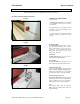
GBC 2064WF-1 FIGURE 12 Operation Manual Nip Pressure Adjustment: The Nip pressure adjustment allows the operator to adjust the downward pressure of the pull rolls and main rolls. Pull Roll Lift Handle: (Fig. 12) Select the setting from the pre-set values and lock latch into the appropriate slot. -Open -1 Inch -3/4 Inch -1/2 Inch -3/8 Inch -3/16 Inch -1/16 Inch -Low Pressure -High Pressure FIGURE 13 Heated Main Roll Lift Handle: (Fig.13) Turn handle clockwise to lower main roll & adjust the Nip Pressure.
GBC 2064WF-1 Operation Manual FIGURE 15 Main Power Cord: (Fig. 15A) The Main Power Cord Plugs into the Main Power Supply. See Power Requirements in the Specs part of the manual for required Voltage and Amperage. A B Foot Switch: (Fig.15B) The Foot Switch allows the operator to run the machine hands free. When the PICO System is not blocked, the Foot Switch will activate the Main Rollers, and the machine will run at the set speed on the Main Control Panel.
GBC 2064WF-1 Operation Manual LCD ERROR SCREENS Set Temp. Current Temp. TOP:150*F TOP:098*F BOT:150*F MODE:FWRD BOT:098*F GAP:000% FIGURE 1: ESW SW PRESSED!!! -Indicates that an Emergency Stop is activated. Locate the Emergency Stop and release it. This will return the machine to normal operating condition. ESW SW PRESSED!!! FIGURE 1. FIGURE 2: SAFETY INTERLOCKED!!! -Indicates that a Table Inter lock is not positioned correctly.
GBC 2064WF-1 Operation Manual SEQUENCE OF OPERATIONS Diagram #1 GBC U.S 2064WF-1 Effect of Fiber Optics on sequence of operation Modes Situation 1 Situation 2 Situation 3 Machine Run Mode Normal operation (No Interruption to any safety circuitry & Fiber optic beam) Interrupted optic beam or opened any safety circuitry. Optic beam cleared + all safety circuitries are closed Control panel: Forward Speed: Zero to Max. Press “Run” push button to switch over from foot switch to the control panel.
GBC 2064WF-1 Operation Manual OPERATING INSTRUCTIONS Film Loading & Threading The top and bottom rolls of laminating film must be of the same width and be present simultaneously. A Small amount of adhesive will “squeeze out” during Lamination. Hardened adhesive deposits can damage the heat rollers. CAUTION: Adhesive will deposit on the rollers if: n ly-i Po • Only one roll is used. • Different widths of rolls are loaded together.
GBC 2064WF-1 Operation Manual Webbing Thermal Film Using Threading Card THERMAL LAMINATE CAUTION: The laminator rollers will be hot and can burn you. For pressure sensitive film (PSA), refer to the section titled WEBBING: USING FILM THREADING CARD FOR PSA FILM. 1. Turn the Main Power ON /OFF to On. 2. Set top and bottom temperature with regards to the film type used. 3. Ensure no brake tension is applied to the film shafts. 4.
GBC 2064WF-1 Operation Manual Webbing PSA Film/Mount Threading Card Adhesive Using The laminator should be cool to the touch before Proceeding. FIGURE 22 REWIND TUBE PSA Film Mount Adhesive FIGURE 23 PSA Film CHILLED ROLLER 1. Turn the Power ON /OFF to On 2. Load the rolls of film as illustrated in (Fig. 22). Ensure no brake tension is applied to the film shafts. 3. Pull the top roll of film down under the idler bar and up to the upper front rewind tube. 4.
GBC 2064WF-1 Operation Manual Start Laminating 1. At this point you should have your laminator webbed with the appropriate material for your application. 2. The feed table should be in the normal operating position. 3. Close the main and Pull roll nips. Rollers should be closed. 4. Speed is set to 3 or less and front () motor direction is selected. 5. Press the start ( ) button. 6. Set main roller pressure between 40% – 60% for laminating by turning the main roll lift handle.
GBC 2064WF-1 Operation Manual Method for Tacking New Film to Existing Film (1) The following describes a method for loading film whereby the existing film present on the heat rollers may be used in place of the threading card to draw the new film through the laminator. The adhesive of the existing film must be tacky or liquefied. Leading edges of the new film will be overlapped onto the tacky adhesive of the old film. The existing film and the new film will be pulled through the laminator together.
GBC 2064WF-1 Operation Manual To unweb the laminator (2) Unweb the laminator if you are changing film widths, cleaning the rollers or have finished using the machine for the day. (1) CAUTION: Do not cut yourself (3) 1. Using a slitter, cut (1) the output from the web (Fig. 28). 2. Cut (2) remaining top film web between the idler bar and heat roller. PSA film cut the release liner too. 3. Cut (3) the film web between the lower film supply and the idler bar (Fig. 28). (2) .......
GBC 2064WF-1 Operation Manual APPLICATIONS Tips for Pre Coating Boards MOUNT ADHESIVE LEADER BOARD TRAILOR BOARD BOARDS FIGURE 30 1. Load the laminator as illustrated in (Fig. 30). Remove chill idler. 2. The width of the roll should not exceed the width of the board by more than 1/2 in. (1.3 cm). 3. Use a leader board to set the main roller and pull roller pressure prior to webbing. 4. Use a leader board to start the run and a trailer board to finish the run. 5.
GBC 2064WF-1 Operation Manual Tips for Creating a Decal 1. Load the laminator as illustrated in Fig. 33. 2. The over laminate may be PSA or thermal type. 3. If using thermal type, pay attention to the Polyin/Poly-out rule. 4. Run a test material prior to running the actual image to ensure flat output. 5. Use minimal brake tension to achieve quality output. 6. Do not web the PSA mount adhesive around the lower web idler.
GBC 2064WF-1 Operation Manual Tips for AccuShield THERMAL FILM IMAGE OPTIONAL SEPERATOR BAR OUTPUT ROLL TO ROLL OPTION KRAFT PAPER OPTION 1. Load the laminator as illustrated in Fig. 36. 2. You must have the Separator bar option to accurately run this material. See your Sales Rep for ordering the Separator Bar. 3. Set Top Temp to 280*F(135*C) and a speed setting no greater than 4. 4. Liner rewind tension will be greater than normal operating standard 5.
GBC 2064WF-1 Operation Manual SPEED / TEMPERATURE CONTROL This is only a general reference guide. Different settings may be suitable as the warm up time, lamination time and materials change. Factors that may affect the speed and temperature parameters; 1. 2. 3. 4. 5. 6. 7. 8. 9. Image length Image width and ink coverage. Ink coverage Paper type Laminate thickness Operating environment Condition of the rollers Line voltage (effects heaters) Using cooling features.
GBC 2064WF-1 Operation Manual Heat -A- -B- FIGURE 39 The “READY” indicator may extinguish if the speed is set too fast for the material being laminated. Either lower the speed setting or press STOP ( ) and wait until the “READY” indicator illuminates. Operation of the laminator for more than thirty minutes at a time may necessitate a lower speed setting. It is recommended that, during periods of long runs, the items being laminated are alternated between thick and thin.
GBC 2064WF-1 Operation Manual MAINTENANCE Caring For The GBC 2064WF-1 Laminator GBC offers Cleaning kits as well as Extended Maintenance Agreements. Contact your local GBC Service Representative or your dealer/distributor for additional information. The only maintenance required by the operator is to periodically clean the heat rollers and schedule semi annual maintenance checks.
GBC 2064WF-1 Operation Manual TROUBLE SHOOTING GUIDE SYMPTOM The control panel display does not illuminate when POWER ON/OFF is in the ON, marked “I”, position POSSIBLE CAUSE CORRECTIVE ACTION Laminator not connected to electrical supply Insert attachment plug into receptacle Heat rollers do not turn when I Blown out fuse. Feed table not properly installed. Press the RUN ( ) button. Pull E-Stop button Heat rollers only turn if I use the “Footswitch”. Laminated items exhibit curling.
GBC 2064WF-1 Operation Manual SERVICE AGREEMENT GBC’s Equipment Maintenance Agreement will insure the quality performance and long life built into your laminator. A service charge for travel time, labor and parts may be incurred for each out of warranty service call. GBC’s Equipment Maintenance Agreement Decreases these expenses and protects your valuable investment. GBC offers several types of agreements to suit your needs and budget. To contact GBC write to: ACCO Brands Inc.