
User Manual


1. Basics
18
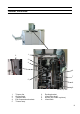
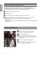
Changing Stapler and Clincher position
Use the allen key in the tool box at position (B) to
loosen each anvil (A).
Move each anvil (A) to the desired position and
tighten the set screws (B) using the allen key.
Loosen the thumb screw (C) for each stapler
assembly. Centre each stapler assembly over
each anvil (A) and thighten the thumb screws (C).
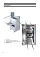
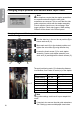
The anvil positioning scale (C) indicates the distance,
in millimetres, from centre to centre (cc) of the staples.
Type of nishing Paper format Setting (cc)
booklet making 5.5”, CD 98
booklet making A5 98
booklet making 8.5”, A4 120 (default position)
booklet making 11”, A3 120 or 200
edge stapling 11”, A4 144 (recommended)
corner stapling 11” 255 (recommended)
corner stapling A4 273 (recommended)
Note
Using other settings could result in poor staple/fold
result.
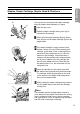
If required, also remove the side guide extensions.
See “Setting up narrow width paper sizes below.
B
A
A
C
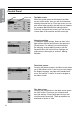
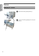
Changing Staple position and Narrow width Paper Sizes
Note
Some situations require that the stapler assemblies
are repositioned and/or that the side guide
extensions are removed. This to avoid that the side
guide extensions collide with the stapler assembly.
If such collision should occur, the message “Side
jogger collision. Check side joggers. Width setting
reseted” will be shown in the control panel.
C