
Logic HE Conventional Flue Combined Controls Installation User Instructions


9
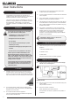
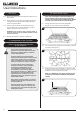
5.4 Ensure that no stones overhang or fill the pilot area, see
Diagram 13, Arrow B.
NOTE: STONES SHOULD NOT BE PLACED DIRECTLY
IN FRONT OF THE PILOT CROSS LIGHTING FLAME.
B
13
5B. Coal Effect Layout
NOTE: CERAMIC PARTS ARE FRAGILE. HANDLE WITH
CARE.
ONLY USE THE CORRECT TYPE AND QUANTITY OF
CERAMIC COMPONENTS. ALWAYS FOLLOW THE FUEL
BED LAYOUT AS STATED IN THESE INSTRUCTIONS.
NEVER CHANGE THE LAYOUT FROM THAT SHOWN
HERE.
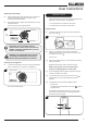
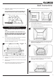
5.5 Ensure the burner cover gasket is positioned on the burner
skin ensuring the holes align with the ports.
Take care as the front left-hand hole is offset compared to
the others, see Diagram 14, arrow A.
A
14
Manual Model
shown
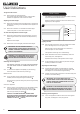
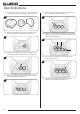
5.6 Place the rear panel against the rear of the box resting on
the shelf.
5.7 Slide one of the side panels into the box ensuring it touches
the rear panel.
5.8 Gently ease the front edge of the side panel behind the
flange so it lies flat against the wall of the box.
5.9 Repeat with the second side panel, see Diagram 15.
15
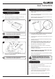
5.10 Locate the top panel on top of the sides and rear by lifting it
up and forward inside the box.
5.11 Slide it backwards and down behind the side panels to rest
on the rear panel, see Diagram 16.
16
5.12 Position the flame baffle centrally on the tray and ensure the
stepped lower edge engages against the rear edge of the
burner skin, see Diagram 17.
17
5.13 Place the front coal centrally in the channel at the front of
the tray. The relationship between the front coal and the
flame baffle is shown in Diagram 18.
18
User Instructions