
Logic HE Conventional Flue Combined Controls Installation User Instructions

21
Installation Instructions
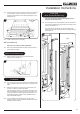
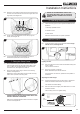
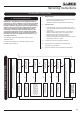
4.12 Connect the gas supply to the inlet connection on the burner
unit and tighten. It may be necessary to support the inlet
connection with another spanner whilst tightening this joint,
see Diagram 12.
12
Manual Model
shown
4.13 Carefully refit the burner assembly.
Slide Control Model only
Take care not to catch the slide mechanism.
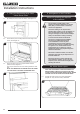
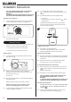
4.14 Secure the 6 screws (Remote and Slide control models), 5
screws (Manual model).
Slide Control Model only
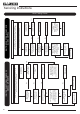
4.15 Refit the spacer and M4 lock nut to secure the slide
mechanism, see Diagram 13.
13
M4 Lock Nut and spacer
All Models
4.16 Turn on the gas supply to the appliance and check for leaks.
Light the appliance and check all joints on the appliance for
leaks.
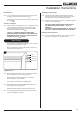
4.17 Remove the sealing screw from the inlet connection and
connect a suitable “U” gauge manometer.
Light the appliance and turn to the maximum position, refer
to the data badge and ensure that the running pressure is
correct. If the pressure varies significantly from that on the
data badge, this may indicate a supply problem and will
require immediate attention.
4.18 Turn the appliance off, disconnect the “U” gauge and
replace the sealing screw. Relight the appliance and check
the sealing screw for leaks.
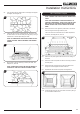
Foam Seal
(Slide Control Models only)
The foam seal must be fitted to the appliance prior to
attaching the decorative front.
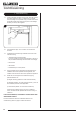
4.19 On the right hand side of the appliance, place the foam seal
in the channel between the glass frame and the slide control
housing, see Diagram 14.
The foam seal must align with the right hand side of the
glass frame and 24mm below the top of the appliance ange,
see Diagram 14.
24
14
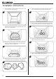
Step 1
Step 2