
Logic HE Balanced Flue Log Installation User Instructions


39
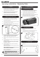
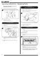
Servicing Instructions - Replacing Parts
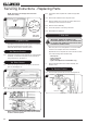
8b. Slide Control
8b.1 To remove the gas valve first remove the thermocouple,
see Diagram 27.
27
8b.2 Undo the pilot pipe from the gas valve, see Diagram 28,
Arrow A.
C
28
A
B
8b.3 Undo the inlet pipe from the gas valve, see Diagram 28,
Arrow B.
8b.4 Undo the main injector feed pipe from the gas valve,
see Diagram 28, Arrow C.
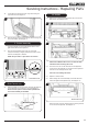
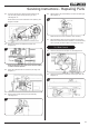
8b.5 Disconnect the 2 leads from the micro-switch, see
Diagram 29.
29
Leads
Bracket
Screw
Micro-switch
8b.6 Undo the screw from the end of the spindle and remove the
bracket, see Diagram 29. Ensure bracket is replaced during
reassembly.
8b.7 Remove the 2 screws from the gas valve, see
Diagram 30.
30
8b.8 Replace in reverse order.
8b.9 Check for gas leaks.
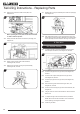
9. Micro-Switch
(Slide Control Models only)
9.1 Disconnect the 2 leads from the Micro-Switch, see
Diagram 31.
31
Leads
Micro-switch
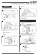
9.2 Remove the screw, bracket, washer & spacer from the
Micro-Switch spindle, see Diagrams 32 & 33.
32
33
Screw
Spacer
Bracket
Washer