
Logic HE Balanced Flue Log Installation User Instructions


38
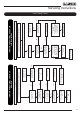
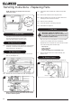
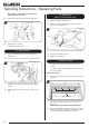
7b.3 Remove the screw and sealant from plate, see
Diagrams 22.
22
Plate
Screw
When replacing the cover plate ensure silicone sealant
is used to seal the aperture.
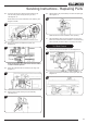
7b.4 Gently bend the tabs back to remove the pilot cage, see
Diagram 23.
23
7b.5 Gently pull the ignition lead off the electrode,
see Diagram 24, Arrow A.
7b.6 Remove the 2 screws securing the pilot assembly,
see Diagram 24, Arrow B.
A
B
24
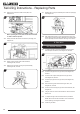
7b.7 Replace with a new pilot assembly and check the spark gap,
see Diagram 25.
25
7b.8 After reassembly check for gas soundness and carry out a
flame failure functional check as detailed in the Fault Finding
chart, especially the time it takes for the mag unit to close.
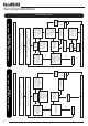
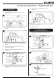
8. Gas Valve
8a. Remote Control
8a.1 To remove the gas valve first remove the red and green
thermocouple connections, see Diagram 26, Arrow A.
26
A
E
White
Green
Red
B CD
Screw
Screw
8a.2 Undo the inlet pipe from the gas valve, see Diagram 26,
Arrow B.
8a.3 Undo the main injector feed pipe from the gas valve,
see Diagram 26, Arrow C.
8a.4 Undo the pilot pipe from the gas valve, see Diagram 26,
Arrow D.
8a.5 Disconnect the ignition lead from the gas valve, see
Diagram 26, Arrow E.
8a.6 Undo 2 screws securing the gas valve to the bracket, see
Diagram 26.
8a.7 The gas valve can now be slid forward to remove from the
burner unit.
8a.8 To replace the gas valve reverse the above procedure.
NOTE: Ensure the correct orientation of the connections
when replacing, see Diagram 26 detail.
8a.9 Check for gas leaks.
Servicing Instructions - Replacing Parts