
Logic HE Balanced Flue Log Installation User Instructions


35
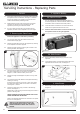
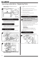
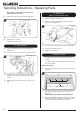
Servicing Instructions - Replacing Parts
4.2 Lift the left hand side of the burner tray, before lifting the
right hand side, see Diagram 5.
5
4.3 Slide the burner tray fully to the left and remove through the
front of the firebox, see Diagram 5.
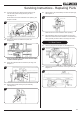
5. Control Assembly
It will be necessary to remove the bottom section of the
glass frame seal from the appliance.
5.1 Push the arrow-headed spring clips out of the body.
It may be necessary to slightly compress the clips to ease
removal, see Diagram 6, Detail A.
NOTE: Only the lower 7 clips need to be removed.
2
1
1
Detail A
6
Remote Model shown
Slide Control only
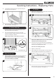
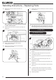
5.2 Remove the M4 lock nut and spacer securing the slider arm
to the appliance and loosen the 2 nuts, see Diagram 7.
Ensure that the spacer is retained and replaced when
the control assembly is reinstalled.
7
M4 Lock Nut and spacer
Nuts
All Models
5.3 Remove the 2 screws positioned either side of the Control
Box bracket, see Diagram 8 & 9.
8
Remote Model
9
Slide Model
Slide Control Models: Take care not to catch the slide
mechanism when removing the burner.
5.4 The burner unit can now be removed from the appliance.
Lift the front of the assembly up and out from the appliance.
Take care not to damage the door seal.
Take care not to damage the liners.
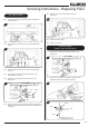
5.5 Replace in reverse order.
5.6 When refitting the Control Assembly ensure that the foam
seal is flat against the appliance body, see Diagram 10.
10
Remote Model shown
Ensure the rear of the tray slides under the retaining bracket
on the rear of the appliance, see Diagram 11.