
Logic HE Balanced Flue Log Installation User Instructions


34
1. General
1.1 All principal components can be replaced without removing
the appliance from its installation, although it is essential
that the gas supply to the appliance is turned off at the
isolation device before proceeding further.
1.2 Before replacing some of the components it will first be
necessary to remove the burner assembly from the
appliance by following the instructions below.
1.3 If for any reason the flue has to be removed from the
appliance, the seal must be replaced in the inner spigot.
2. Removing the Glass Frame
Ensure the appliance is cold before proceeding.
2.1 Turn the gas supply off at the isolation device. Then
disconnect the supply pipe.
2.2 Remove the decorative front from the appliance by referring
to the separate instructions supplied.
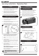
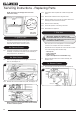
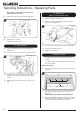
2.3 Remove the glass frame by removing the 4 screws in the
retaining bracket, see Diagram 1.
Detail A
A
1
2.4 Tilt the top of the glass frame forward and disengage
the lower location tabs from the slots in the firebox, see
Diagram 1, Detail A. Place carefully to one side.
2.5 Remove the logs and Embaglow and place on a dry, clean
surface.
2.6 The glass frame must be refitted to the appliance following
cleaning or servicing.
Ensure that the rope seal on the box is intact, then locate
the glass frame location tabs into the slots on the firebox,
see Diagram 1, Detail A.
2.7 Secure the glass frame using 4 screws in the retaining
bracket, see Diagram 1.
Replace ALL of the securing screws ensuring that a screw is
present in all fixing slots.
NEVER OPERATE THE APPLIANCE WHEN THE GLASS
FRAME IS REMOVED OR BROKEN.
Refer to the separate decorative front instructions to replace
the front on the appliance.
UNDER NO CIRCUMSTANCES SHOULD THE
APPLIANCE BE USED IF ANY OF THE GLASS
FRAME RETAINING SCREWS ARE LOOSE OR
MISSING.
Servicing Instructions - Replacing Parts
3. Appliance Battery
3a. Remote Control
It is not necessary to remove the appliance battery to
service the appliance, however the Power Switch on the
Control Box must be switched to the OFF position.
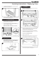
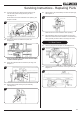
3a.1 The Power Switch is located on the Control Box at the
bottom of the appliance behind the ash cover.
3a.2 Slide the white Power Switch on the Control Box to the
OFF position before servicing the appliance.
2
Power Switch
3b. Slide Control
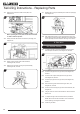
3b.1 Remove the battery before carrying out work on this
appliance.
3b.2 The appliance battery is located at the bottom left of the
appliance behind the ash cover, see Diagram 3.
3
9V Battery
Ignition Unit
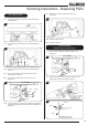
4. Main Burner
4.1 Remove the 2 screws at the front of the burner tray, see
Diagram 4.
4