
Logic HE Balanced Flue Log Installation User Instructions

25
Installation Instructions
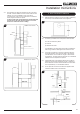
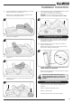
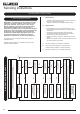
9.4 Log B is positioned on the right hand locating pin, and rests
against the back liner, see Diagram 16.
Nat Gas only - ensure that the left hand side rests on the
burner bracket, see Diagrams 15 & 16.
16
B
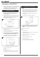
9.5 Log C rests on Log A and the front tray with the locating pin
facing up, see Diagram 17.
17
C
9.6 Log D ts onto the locating pin and rests on Log B, see
Diagram 18.
18
D
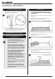
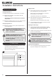
9.7 Position the 2 embers in the front right and back left corners,
see Diagram 19.
19
9.8 Sparingly spread an amount of the Embaglow bres provided
on the sections highlighted, see Diagram 20.
Take care not to use more than half a packet per
application.
WARNING - DO NOT PLACE NEAR THE PILOT AREA.
20
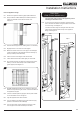
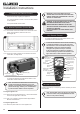
10. Fitting the Glass Frame
10.1 Ensure that the rope seal on the box is intact, then locate
the glass frame location tabs into the slots on the firebox,
see Diagram 21, Detail A.
10.2 Secure the glass frame using 4 screws in the retaining
bracket, see Diagram 21.
Replace ALL of the glass frame securing screws ensuring
that a screw is present in all fixing slots.
Detail A
A
21
NEVER OPERATE THE APPLIANCE WHEN THE GLASS
FRAME IS REMOVED OR BROKEN.
Refer to the separate decorative front Instructions to replace
the front on the appliance.
UNDER NO CIRCUMSTANCES SHOULD THE
APPLIANCE BE USED IF ANY OF THE GLASS
FRAME RETAINING SCREWS ARE LOOSE OR
MISSING.
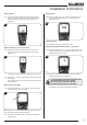
Operating the Appliance
There are 2 types of control systems available for this
appliance:
Section 11 Manual and Remote Control
Section 12. Slide Control
Follow the relevant section for specific operation.