
Logic HE Balanced Flue Log Installation User Instructions

20
Installation Instructions
1. Safety Precautions
1.1 For your own and other’s safety, you must install this
appliance according to local and national codes of practice.
Failure to install the appliance correctly could lead to
prosecution. Read these instructions before installing
and using this appliance.
1.2 These instructions must be left intact with the user.
1.3 Do not attempt to burn rubbish on this appliance.
1.4 Keep all plastic bags away from young children.
1.5 Do not place any object on or near to the appliance and
allow adequate clearance above the appliance.
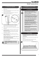
IF THE APPLIANCE IS EXTINGUISHED OR GOES OUT IN
USE, WAIT 3 MINUTES BEFORE ATTEMPTING TO
RELIGHT THE APPLIANCE.
IMPORTANT: REFER TO DATA BADGE AND
TECHNICAL SPECIFICATION AT THE FRONT OF THE
MANUAL TO ENSURE THE APPLIANCE IS
CORRECTLY ADJUSTED FOR THE GAS TYPE AND
CATEGORY APPLICABLE IN THE COUNTRY OF USE.
FOR DETAILS OF CHANGING BETWEEN GAS
TYPES REFER TO SERVICING, SECTION 13,
REPLACING PARTS.
Unpacking
1.6 Remove the appliance from its packaging, and check that it
is complete and undamaged.
Put the loose ceramic parts to one side so that they are not
damaged during installation.
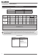
2. Installation of the Gas Supply
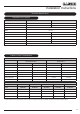
For specific gas types and working pressures see
Technical Specification, page 14.
TO CHANGE FROM ONE GAS TYPE TO ANOTHER A
COMPLETE ENGINE ASSEMBLY AND DATA BADGE WILL
BE REQUIRED. SEE SECTION 10 REPLACING PARTS.
2.1 Before installation, ensure that the local distribution
conditions (identification of the type of gas and pressure)
and the adjustment of the appliance are compatible. See
Technical Specification on page 14.
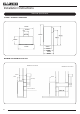
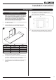
2.2 The position of the gas inlet pipe is shown, see Diagram 1.
35mm
120mm
1
2.3 All supply pipes must be purged of any debris that may have
entered, prior to connection to the appliance.
2.4 The gas supply enters through the silicone panel located on
the rear of the outer box. This will need to be slit with a
sharp knife prior to passing the supply pipe through.
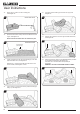
3. Preparing the Appliance
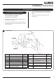
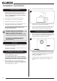
3.1 Remove the backing from the self-adhesive silicone sealing
strip and apply to the rear flange of the firebox ensuring that
the strip is positioned as close to the outer edge as is
practically possible, see Diagram 2, Arrow A.
B
A
2
3.2 Gas pipe entry must come through the rear right-hand side
of the box. The rubber seal must be cut using a sharp knife
to allow the isolating elbow to pass through it. Ensure the
rubber is not damaged when doing this,
see Diagram 2, Arrow B.
3.3 A means of isolation is provided with the appliance. This
must be fitted to the supply pipe prior to installing the
firebox.