
Logic HE Balanced Flue Combined Controls Installation User Instructions

34
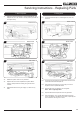
Slide Control
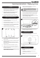
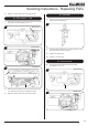
2.16 Remove the battery before carrying out work on this
appliance.
The appliance battery is located at the bottom left of the
appliance behind the ash cover, see Diagram 4.
4
9V Battery
Ignition Unit
2.17 Remove the 2 lower screws positioned either side of the
control valve bracket, see Diagram 5.
5
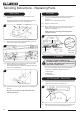
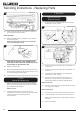
2.18 Remove the M4 lock nut and spacer securing the slider
arm to the appliance, see Diagram 6.
Ensure that the spacer is retained and replaced when the
burner unit is reassembled.
6
M4 Lock Nut and spacer
2.19 The burner unit can now be removed from the appliance,
see 2.20.
Take care not to catch the slide mechanism when
removing the burner.
All Models
2.20 The burner unit can now be removed from the appliance.
Lift the front of the assembly up and out from the
appliance.
Take care not to damage the door seal.
2.21 Replace in reverse order.
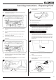
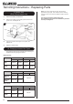
2.22 When refitting the burner unit, ensure the rear of the tray
slides under the retaining bracket on the rear of the
appliance, see Diagram 7.
NOTE: The burner unit and pipe work have been
removed for clarity.
Burner
Tray
Retaining
Bracket
Detail A
Retaining
Bracket
Burner
Tray
7
Manual Control
model shown
3. Pilot Unit
IMPORTANT: UNDER THE TERMS OF THE
EXTENDED WARRANTY IT WILL BE COMPULSORY
TO CHANGE THE COMPLETE PILOT UNIT ON THIS
APPLIANCE IN YEARS 2 AND 4.
The pilot unit assembly consists of three components
which can be individually changed, these are:-
3a. Pilot Injector
3b. Electrode
3c. Thermocouple
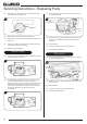
3a. Pilot Injector - Stone Effect
3.1 Undo the pilot pipe from the bulkhead fitting and from the
underside of the pilot unit, see Diagram 8.
8
3.2 Remove the pipe and the injector drops out from the pilot
unit. Take care not to loose or damage the injector.
Servicing Instructions - Replacing Parts