
Stockton Inset Front Installation User Instructions


2
Covering frame model numbers:
Stockton 7 Inset
Logic HE 901-488
1. General
1.1 These instructions are supplementary to, and must be read
in conjunction with, the installation instructions supplied with
the appliance. Read both thoroughly before installation.
1.2 Fitting of this decorative front should be carried out after
the appliance has been installed and commissioning tests
completed.
1.3 Ensure that these supplementary instructions are attached
to the Installation Instructions and leave with the user.
2. Fitting the Decorative Front
BEFORE FITTING THE STOCKTON FRONT THE
APPLIANCE MUST BE SECURED FIRMLY TO
THE FIREPLACE OPENING AND THE HEARTH.
DUE TO THE WEIGHT OF THE FRONT IT IS
ADVISABLE TO SECURE THE APPLIANCE TO
THE FIREPLACE OPENING USING THE
SCREWS AND RAWL PLUGS SUPPLIED.
WHEN USING THE CABLE FIXING METHOD, THE
TENSION ON THE CABLES MUST BE RECHECKED
WHEN THE STOCKTON FRONT HAS BEEN FITTED
AND IF NECESSARY INCREASED.
2.1 Ensure the appliance is installed firmly in position.
2.2 Remove the Stockton Inset front from the packaging.
Slide Controls Models only
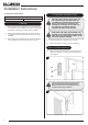
2.3 Remove the cast infill from the front by unscrewing the 2
screws. This provides a cutout for the slide mechanism,
see Diagram 1.
1
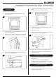
Caution: When fitting the front ensure that the
cutout fits around the slide mechanism, see
Diagram 2. Take care not to damage the slide
control handle during installation.
2
Installation Instructions