
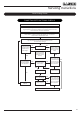
Logic HE Conventional Flue Combined Controls Installation User Instructions


38
Servicing Instructions - Replacing Parts
Slide Control
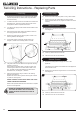
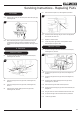
6.18 To remove the gas valve first remove the thermocouple,
see Diagram 28, Arrow A.
D
28
A
B
C
6.19 Undo the pilot pipe from the gas valve, see Diagram 28,
Arrow B.
6.20 Undo the inlet pipe from the gas valve, see Diagram 28,
Arrow C.
6.21 Undo the main injector feed pipe from the gas valve,
see Diagram 28, Arrow D.
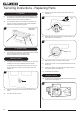
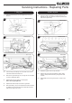
6.22 Disconnect the 2 leads from the micro-switch, see
Diagram 29.
29
Leads
Bracket
Micro-switch
6.23 Undo the screw from the end of the spindle and remove the
bracket, see Diagram 29. Ensure bracket is replaced during
reassembly.
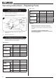
6.24 Remove the front baffle by undoing the screw securing it to
the burner unit, see Diagram 30.
Ensure the baffle is replaced during re-assembly.
30
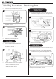
6.25 Remove the front channel from the top of the burner
unit by undoing the 2 screws, see Diagram 31.
Note: When replacing the front channel ensure that the
end with the 2 holes is located to the right side of the
burner unit with the taller face to the front.
31
Screws
6.26 Undo the 2 screws securing the bracket to the bottom
of the burner unit, see Diagram 32.
32
Screws
6.27 Undo 2 screws securing the gas valve to the bracket,
see Diagram 33.
Screws
33
6.28 Replace in reverse order.
6.29 Check for gas leaks.