
Logic HE Conventional Flue Combined Controls Installation User Instructions


34
2. General
2.1 To service any of the following parts of the appliance, it will
be necessary to remove the burner unit from the firebox. To
remove the burner refer to Servicing Section 1.
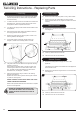
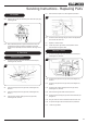
2.2 The heat shield needs to be removed from the burner for
servicing. To do this remove the three screws indicated in
Diagram 9 and slide the shield forward.
9
Manual Control
Model shown
3. Ignition Lead
3.1 The different control versions of this appliance have different
servicing requirements for the Ignition Lead.
Follow the relevant section for each product.
Manual Control
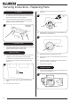
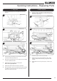
3.2 The Ignition lead and Piezo on this appliance are part of one
complete unit and must be replaced at the same time.
To replace the unit remove the control knob on the front of
the valve cover and undo the nut securing the valve, see
Diagram 10.
10
3.3 Disconnect all other valve connections on the rear of the
valve.
3.4 The valve will now come off.
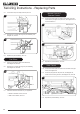
3.5 Remove the clip from around the front of the valve, see
Diagram 11.
Clip
Ignition
lead
Piezo
11
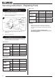
3.6 Rotate the Piezo anti-clockwise until the tab appears in the
slot at the front, see Diagram 12.
Tab
Piezo
12
3.7 Withdraw the Piezo unit forward from the valve.
3.8 Replace with a new unit and re-assemble the valve into the
burner unit.
3.9 Check the operation of the Piezo ignitor making sure that
both ignition ‘clicks’ are functioning.
3.10 Reassemble the appliance.
Remote Control
3.11 Undo the single screw that secures the left hand side of the
control cover, see Diagram 13.
13
Servicing Instructions - Replacing Parts