
Logic HE Conventional Flue Combined Controls Installation User Instructions

20
4. Installation of the Appliance
4.1 Ensure that the fireplace opening is in compliance with
Section 2 Site Requirements then proceed as follows:
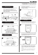
A) Cable Retention Method
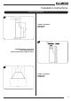
4.2 Mark the position of the 4 fixing holes on the rear of the
fireplace opening and drill the holes using a 7mm masonry
drill bit. Insert the 4 steel expansion plugs and screw the
eyebolts in as far as possible leaving the eye horizontal,
see Diagram 8.
8
4.3 Pass the 2 cables through the holes in the bracket on the
back of the firebox and pull taut so that the stop ends sit
tightly against the top of the bracket, see Diagram 9.
9
4.4 Pass the cables vertically through the 2 sets of eyebolts and
thread the ends through the holes in the lower back of the
firebox. Pass the gas supply pipe through the hole in the
rubber seal (refer to section 4.11) and push the appliance
into place.
4.5 Thread the cables through the tensioner bolts and push
the threaded portions through the holes in the firebox so
that the lock nut sits against the back wall (ensure that the
nut is screwed fully up to the head of the tensioner to allow
maximum adjustment).
Installation Instructions
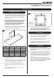
4.6 Slide the locking nipples onto the cables, pull the cables taut
and tighten the locking screw. Adjust the lock nuts using a
10mm spanner until the silicone sealing strip forms a tight
seal between the fireplace opening and the firebox flange,
see Diagram 10.
10
4.7 Coil up the surplus cable and locate in the back of the
firebox.
NEVER SHORTEN THE CABLES, THEY WILL BE
REQUIRED WHEN SERVICING THE APPLIANCE.
4.8 Replace the lower cover plate.
Note: The cable adjuster may need to be tucked upward in
order to fit the lower cover plate.
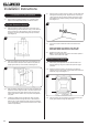
B) Screw Fixing Method
4.9 Alternatively, this appliance can be secured back to the
fireplace opening using the screws and expansion plugs
provided.
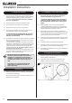
4.10 Place the firebox centrally in the opening and mark the
positions of the 4 fixing holes. Drill the holes and insert the 4
expansion plugs, see Diagram 11.
11
4.11 Offer the firebox into the opening and ensure that the gas
supply pipe passes through the rubber seal.