
Logic HE Balanced Flue Log Installation User Instructions


40
Servicing Instructions - Replacing Parts
When replacing ensure that the components are
assembled in the same order.
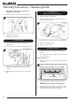
9.3 Remove the circlip from the spindle, see Diagram 34.
34
Circlip
Micro-Switch
9.4 Replace the micro-switch.
Reassemble in reverse order.
10. Main Injector
10.1 Undo the compression nut from the feed pipe, see
Diagram 35, A
10.2 Undo the lock nut from the injector, see Diagram 35, B.
A
B
35
Remote Model shown
10.3 Replace with the correct replacement injector. When
ordering, always state the model, gas type and serial
number.
10.4 Reassemble and turn the gas supply on, check for any
leaks.
11. Ignition Unit
(Slide Control Models only)
11.1 Remove the battery, see Section 3.
11.2 Remove the 2 leads and the pilot ignition lead from the
ignition unit, see Diagram 36.
Leads
36
Pilot Ignition
Lead
Screw
11.3 Undo the screw securing the unit in place, see Diagram 36.
11.4 Slide the unit forward to remove.
11.5 Replace in reverse order.
12. Baffle & Liners
The Baffle and Liners do not need to be removed for
servicing.
This appliance fitted with twin baffle system, consisting of a
front and rear baffle.
FRONT TOP BAFFLE
12.1 Undo the 4 screws securing it to the roof of the firebox, see
Diagram 37.
Screws
37
Rear Top Baffle
12.2 The Front Top Baffle can now be removed by lowering the
front edge and pulling forward through the front of the
appliance.
TAKE CARE NOT TO DAMAGE THE SIDE PANELS.
12.3 Note: When replacing the baffle ensure that the rear edge
locates above the rear Top Baffle, see Diagram 37. Take
care not to damage the rope seal pins and liners.