
Logic HE Range Conventional Flue Log Effect Installation User Instructions

37
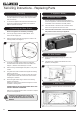
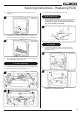
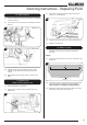
7b. Slide Control
7b.1 Gently pull the ignition lead off the electrode,
see Diagram 16, Arrow A.
7b.2 Remove the 2 screws securing the pilot assembly,
see Diagram 16, Arrow B.
A
B
16
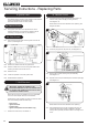
7b.3 Undo the thermocouple connection from the gas valve, see
Diagrams 16 & 17.
7b.4 Undo the pilot pipe from the pilot unit, see Diagrams 16 &
17, arrow A and from the gas valve, see Diagrams 16 & 17,
arrow B.
Thermocouple
17
Pilot Pipe
B
A
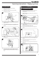
7b.5 Replace with a new pilot assembly and check the spark gap,
see Diagram 18.
18
7b.6 After reassembly check for gas soundness and carry out
a flame failure functional check as detailed in the Fault
Finding chart, especially the time it takes for the mag unit to
close.
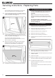
8. Gas Valve
8a. Remote Control
8a.1 Unplug the red and green thermocouple connections (A)
and the white ignition lead (B) from the gas valve,
see Diagrams 13.
NOTE: Ensure the correct orientation when replacing, see
Diagram 19 detail.
19
A
A
B
White
Green
Red
8a.2 Carefully turn the Control Assembly over to access the Gas
Valve connections,
Take care not to damage the Pilot unit.
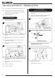
8a.3 Undo the pilot pipe from the gas valve, see Diagram 20,
Arrow A.
20
A
C
B
8a.4 Undo the inlet pipe from the gas valve, see Diagram 20,
Arrow B.
8a.5 Undo the main injector feed pipe from the gas valve,
see Diagram 20, Arrow C.
8a.6 Undo 2 screws securing the gas valve to the bracket, see
Diagram 21.
Screws
21
Servicing Instructions - Replacing Parts