
Logic HE Conventional Flue Combined Controls Installation User Instructions


33
Servicing Instructions - Replacing Parts
Slide Control
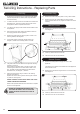
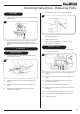
1.17 Remove the battery before carrying out work on this
appliance.
The battery box is located at the bottom left of the appliance
behind the ash cover, see Diagram 4.
4
9V Battery
Ignition
Unit
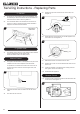
1.18 Remove the 6 screws securing the burner unit to the firebox,
see Diagram 5.
5
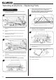
1.19 Remove the M4 lock nut and spacer securing the slide arm
to the appliance, see Diagram 6.
Ensure that the spacer is retained and replaced when the
burner unit is reinstalled.
6
M4 Lock Nut and spacer
1.20 Clean any debris from the burner skin.
1.21 The burner unit can now be removed.
Take care not to catch the slide mechanism.
White Stone Effect Only
1.22 Remove the white stones and place on a clean dry surface.
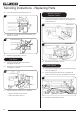
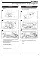
1.23 Remove the two decorative panel securing clamps,
see Diagram 7.
7
1.24 Carefully remove the enamel back panel by rotating it out of
the firebox.
TAKE EXTREME CARE WHILST REMOVING THESE
PANELS NOT TO SCRATCH OR CHIP THE PANEL ON
THE SIDES OF THE FIREBOX.
1.25 Remove the 5 screws securing the burner:
8
1.26 Gently slide the whole burner assembly forward.
1.27 Clean any debris from the burner skin.