
Logic HE Conventional Flue Combined Controls Installation User Instructions


32
1. Servicing
As part of the annual service, the space behind the firebox
must be inspected for any debris, which may have fallen
down the chimney.
1.1 To remove the main burner from the firebox first remove the
decorative front. There are 2 screws securing the front to
the appliance. Refer to separate instructions.
1.2 Turn off the gas supply at the isolation device located under
the appliance.
1.3 Disconnect the gas supply leaving the isolation device on
the supply pipe and not the appliance.
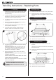
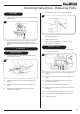
1.4 Remove the glass frame by removing the 4 screws in the
retaining bracket, see Diagram 1.
1.5 Lift the glass frame off the lower locations tabs, see
Diagram 1, Detail A and carefully place to one side.
Detail A
A
1
1.6 The glass frame must be refitted to the appliance following
cleaning or servicing.
Ensure that the fibre glass seal on the box is intact, then
lower the glass frame into the lower location tabs on the
box. The tabs should locate between the glass and the
decorative front, see Diagram 1, Detail A.
1.7 Secure the glass frame using 4 screws in the retaining
bracket, see Diagram 1.
Replace ALL of the securing screws ensuring that a screw
is present in all fixing slots.
NEVER OPERATE THE APPLIANCE WHEN THE GLASS
FRAME IS REMOVED OR BROKEN.
Refer to the separate decorative front instructions to replace
the front on the appliance.
UNDER NO CIRCUMSTANCES SHOULD THE
APPLIANCE BE USED IF ANY OF THE GLASS
FRAME RETAINING SCREWS ARE LOOSE OR
MISSING.
Servicing Instructions - Replacing Parts
Coal Effect Only
1.8 Remove the loose coals, and place on a dry, clean surface.
1.9 Remove the front coal, flame baffle and all the ceramic
liners. All these items are very fragile and need to be stored
carefully.
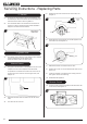
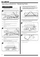
Manual Control
1.10 Remove the 5 screws securing the burner unit to the firebox,
see Diagram 2.
2
1.11 Clean any debris from the burner skin.
1.12 The burner unit can now be removed.
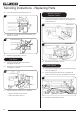
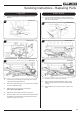
Remote Control
1.13 Remove the battery before carrying out work on this
appliance.
The battery box is located at the bottom left of the appliance
behind the ash cover.
1.14 Remove the 6 screws securing the burner unit to the firebox,
see Diagram 3.
3
1.15 Clean any debris from the burner skin.
1.16 The burner unit can now be removed.