
Logic HE Conventional Flue Combined Controls Installation User Instructions

19
Installation Instructions
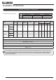
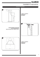
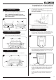
Manual Control
3.3 Remove the 5 burner retaining screws and withdraw the
burner unit from its location, see Diagram 2.
NOTE: IF REMOVING THE BURNER, IT WILL BE
NECESSARY TO REMOVE THE DECORATIVE INNER
PANEL, SEE SECTION 5.
2
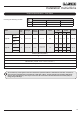
Remote Control
3.4 Remove the 6 burner retaining screws and withdraw the
burner unit from its location, see Diagram 3.
3
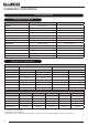
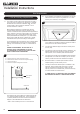
Slide Control
3.5 Remove the 6 burner retaining screws, see Diagram 4.
4
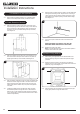
3.6 Remove the M4 lock nut and spacer securing the slider arm
to the appliance, see Diagram 5.
Ensure that the spacer is retained and replaced when
the engine is reinstalled.
5
M4 Lock Nut and spacer
Withdraw the burner unit from its location.
Take care not to catch the slide mechanism.
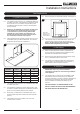
All Models
3.7 Decide on the retention method, if the cable retention kit is
to be used then remove the two knockout holes on the rear
of the box using a sharp hammer blow, see Diagram 6.
6
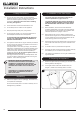
3.8 Remove the backing from the self-adhesive silicone sealing
strip and apply to the rear flange of the firebox ensuring that
it is positioned as close to the outer edge as is practically
possible, see Diagram 7, Arrow A.
A
B
7
3.9 Gas pipe entry must come through the right-hand side of
the box. The rubber seal must be cut using a sharp knife
to allow the isolating elbow to pass through it. Ensure the
rubber is not damaged when doing this, see Diagram 7,
Arrow B.
A means of isolation is provided with the appliance. This
must be fitted to the supply pipe prior to installing the
firebox.