
Logic HE Conventional Flue Combined Controls Installation User Instructions

18
1. Safety Precautions
1.1 For your own and other’s safety, you must install this
appliance according to local and national codes of practice.
Failure to install the appliance correctly could lead to
prosecution. Read these instructions before installing
and using this appliance.
1.2 These instructions must be left intact with the user.
1.3 Do not attempt to burn rubbish on this appliance.
1.4 Keep all plastic bags away from young children.
1.5 Do not place any object on or near to the appliance and
allow adequate clearance above the appliance.
IF THE APPLIANCE IS EXTINGUISHED OR GOES OUT
IN USE, WAIT 3 MINUTES BEFORE ATTEMPTING TO
RELIGHT THE APPLIANCE.
1.6 The appliance is fitted with an oxygen sensitive pilot that will
act to cut off the gas supply to the appliance in the event of
incorrect operation of the flue.
If the system acts to shut off the gas supply, this indicates
that there is insufficient flue pull. Continued operation of this
safety device means that there may be a serious problem
with the flue system, and this should be inspected by a
qualified gas engineer. Do not use the appliance until an
engineer says it is safe to do so.
The oxygen sensitive pilot must not be tampered with. Use
only genuine Gazco replacement parts when servicing the
appliance - refer to Servicing section.
IMPORTANT: REFER TO DATA BADGE AND
TECHNICAL SPECIFICATION AT THE FRONT OF
THE MANUAL TO ENSURE THE APPLIANCE IS
CORRECTLY ADJUSTED FOR THE GAS TYPE AND
CATEGORY APPLICABLE IN THE COUNTRY OF
USE.
FOR DETAILS OF CHANGING BETWEEN GAS
TYPES REFER TO SERVICING, SECTION 10,
REPLACING PARTS.
Unpacking
1.7 Remove the appliance from its packaging, and check that it
is complete and undamaged.
Put the loose ceramic parts to one side so that they are not
damaged during installation.
Installation Instructions
2. Installation of the Gas Supply
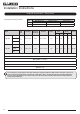
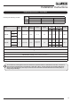
For specific gas types and working pressures see
Technical Specifications, pages 12 and 13.
TO CHANGE FROM ONE GAS TYPE TO ANOTHER A
COMPLETE ENGINE ASSEMBLY AND DATA BADGE
WILL BE REQUIRED. SEE SECTION 10 REPLACING
PARTS.
2.1 Before installation, ensure that the local distribution
conditions (identification of the type of gas and pressure)
and the adjustment of the appliance are compatible. See
Technical Specification on pages 12 and 13.
2.2 Ensure that the gas supply is capable of delivering the
required amount of gas and is in accordance with the rules
in force. Please refer to the technical specification for the
correct working pressure for the gas used.
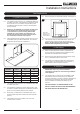
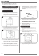
2.3 Soft copper tubing and soft soldered joints can be used but
must not be closer than 50mm (2”) to the underside of the
burner.
2.4 An isolation device is provided with the appliance.
2.5 All supply gas pipes must be purged of any debris that may
have entered, prior to connection to the appliance.
2.6 This appliance is intended for use on a gas installation with
a governed meter.
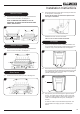
3. Preparing the Appliance
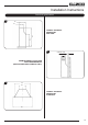
3.1 Remove the glass frame by unscrewing the 4 screws in the
retaining bracket, see Diagram 1.
3.2 Lift the glass frame off the lower locations tabs, see
Diagram 1, Detail A and carefully place to one side.
Detail A
A
1