
Logic HE Balanced Flue Log Installation User Instructions


23
Installation Instructions
Flue and Appliance Fixings
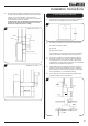
6.11 Position the appliance observing appropriate clearances.
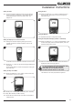
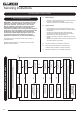
6.12 Apply a bead of suitable weatherproof sealant (silicone or
similar) to perimeter of back face of terminal, see
Diagram 9.
A
9
6.13 Feed the flue through the wall, making sure it runs smoothly.
6.14 Engage the flue in the inner and outer spigots.
6.15 Make sure rubber seal on the inner spigot is not damaged,
it may be necessary to lubricate the seals with washing up
liquid (or similar) to ease assembly.
6.16 Insert 4 screws in the flanges of the flue terminal.
6.17 Check sealant has formed a water-tight joint to the wall.
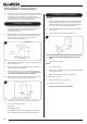
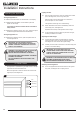
6.18 Any terminal less than 2m above any access (level ground,
balcony or flat roof with access) must be fitted with the
guard supplied, see Diagram 10.
10
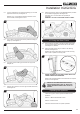
6.19 PURGE THE SUPPLY PIPE. This is essential to expel any
debris that may block the gas controls. Connect the elbow to
the appliance inlet pipe.
6.20 Connect a suitable pressure gauge to the test point located
on the inlet elbow and turn the gas on.
6.21 Light the appliance and check for leaks.
6.22 Turn the appliance to maximum and check that the supply
pressure is as stated on the databadge
6.23 Turn the gas supply off and replace the test point screw.
Turn the gas on and check the test point for leaks.
Foam Seal
(Slide Control Models only)
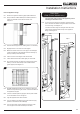
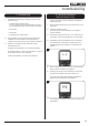
The foam seal must be fitted to the appliance prior to
attaching the decorative front.
6.24 On the right hand side of the appliance, place the foam
seal in the channel between the glass frame and the slide
control housing, see Diagram 11.
The foam seal must align with the right hand side of the
glass frame and 24mm below the top of the appliance
ange, see Diagram 11.
24
11
Step 1
Step 2