
Logic HE Range Conventional Flue Log Effect Installation User Instructions

23
Installation Instructions
Foam Seal
(Slide Control Models only)
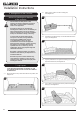
The foam seal must be fitted to the appliance prior to
attaching the decorative front.
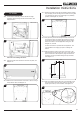
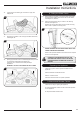
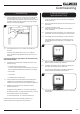
4b.6 On the right hand side of the appliance, place the foam
seal in the channel between the glass frame and the slide
control housing, see Diagram 20.
The foam seal must align with the right hand side of the
glass frame and 24mm below the top of the appliance
ange, see Diagram 20.
24
20
Step 1
Step 2
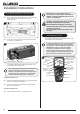
5. Gas Supply
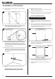
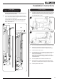
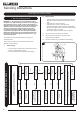
5.1 Connect the gas supply to the inlet connection on the control
assembly and tighten. It may be necessary to support the
inlet connection with another spanner whilst tightening this
joint, see Diagrams 21 & 22.
21
Slide Control
22
Remote
Control
5.2 Turn on the gas supply to the appliance and check for leaks.
5.3 Remove the pressure test point screw from the inlet
connection and connect a suitable “U” gauge manometer.
5.4 Carefully refit the main burner.
5.5 Light the appliance, turn to maximum (Remote models light
on maximum) and check that the supply pressure is as
stated on the databadge.
If the pressure varies significantly from that on the data
badge, this may indicate a supply problem and will require
immediate attention.
5.6 Turn the appliance off and remove the main burner.
5.7 Disconnect the “U” gauge and replace the pressure test
point screw. Check the pressure test point screw for leaks.
5.8 Carefully refit the main burner.