
Logic HE Range Conventional Flue Log Effect Installation User Instructions

21
All Models
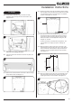
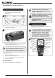
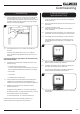
4a.8 Lift the control assembly, move to the left and angle
forward to remove through the front of the firebox, see
Diagrams 8 & 9.
8
Slide Control
9
Remote Control
Take care not to damage the liners.
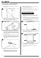
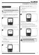
4a.9 Undo the screws and remove the convector air panel, see
Diagram 10.
10
4a.10 Remove the 2 knockout holes on the rear of the box using a
sharp hammer blow, see Diagram 11.
11
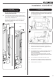
4a.11 Remove the backing from the self-adhesive silicone sealing
strip and apply to the rear flange of the firebox ensuring that
it is positioned as close to the outer edge as is practically
possible, see Diagram 12, Arrow A.
A
B
12
4a.12 Gas pipe entry must come through the rear of the box on
the right-hand side. The rubber seal must be cut using a
sharp knife to allow the isolating elbow to pass through it.
Ensure the rubber is not damaged when doing this, see
Diagram 12, Arrow B.
A means of isolation is provided with the appliance. This
must be fitted to the supply pipe prior to installing the
firebox.
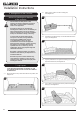
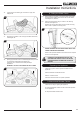
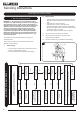
4a.13 Mark the position of the 4 fixing holes on the rear of the
fireplace opening and drill the holes using a 7mm masonry
drill bit. Insert the 4 steel expansion plugs and screw the
eyebolts in as far as possible leaving the eye horizontal,
see Diagram 13.
13
170
170
25
475
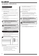
4a.14 Pass the 2 cables through the holes in the brackets on the
back of the firebox and pull taut so that the stop ends sit
tightly against the top of the brackets, see Diagram 14.
14
Installation Instructions