
Logic HE Balanced Flue Log Installation User Instructions

22
Installation Instructions
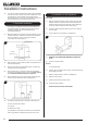
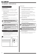
4.6 The void into which the appliance is fitted must be ventilated
to prevent a build up of heat. If the void is sealed then it will
be necessary to fit vents at both low and high levels of
approximately 50cm
2
. These vents should take cold air from
the room and return warm air back into the room.
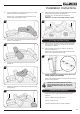
5. Recessed Installation
This method of installation requires structural alteration to
the intended location. A suitable supporting lintel must be
installed to maintain the structural integrity of the
surrounding blockwork.
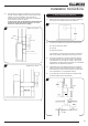
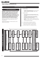
5.1 Mark the position of the lintel so that it sits centrally over the
intended installation. Remove the blockwork and install the
lintel using mortar to ensure a strong bond with the
surrounding wall, see Diagram 6.
6
560-575
Supporting Lintel
410-450
Finished
Hearth Level
5.2 With the lintel in position mark the width of the aperture and
remove the blockwork.
5.3 Seal the cavity with non combustible board, to prevent any
insulation touching the appliance.
5.4 Ensure that there is a minimum of 5mm gap left between
the back of the appliance and the outer wall. There must be
no combustible materials behind this appliance.
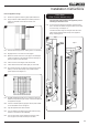
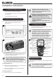
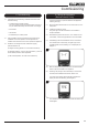
5.5 Mark the position of the flue on the wall by measuring from
the top of the finished hearth level, see Diagram 7.
7
5.6 A 152mm (6’) diameter hole is required to install the flue.
This can be achieved by either:
a) Core drill
b) Hammer and chisel
It is advisable to drill small holes around the circumference
when using method b. Make good both ends of the hole.
6. Installation of the Appliance
Flue Length
6.1 With the appliance secured in place, (minimum 10mm gap
between the back of appliance and the wall) measure the
distance from the back of the appliance to the outside face
of the wall. Deduct 18mm from this measurement.
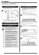
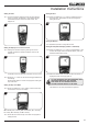
6.2 Insert the square cardboard sleeve into the flue to support
the inner tube.
6.3 Cut through the flue and sleeve, see Diagram 8.
8
6.4 REMOVE THE CARDBOARD REMNANTS FROM THE
FLUE.
6.5 File the cut edges smooth.
Terminal
On the outside wall:
6.6 Position the flue assembly into the hole. The terminal should
be flat against the wall.
6.7 Make sure the terminal is vertical, see Diagram 8.
6.8 Mark the 4 fixing holes.
6.9 Remove the terminal to drill the holes.
6.10 Insert wall plugs supplied.
DO NOT FIX THE FLUE AT THIS STAGE.