
Logic HE Balanced Flue Combined Controls Installation User Instructions


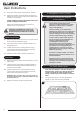


9
User Instructions
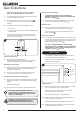
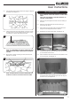
5.2 Lean the white stones against the burner ledges to disguise
the ledges, see Diagram 13.
13
5.3 Check that the port area, see Diagram 14, Arrow A is clear
of white stones. This can be easily done by gently running
a screwdriver or similar object along this area.
A
14
NOTE: IT IS IMPORTANT THE WHITE STONES DO NOT
COVER THE PORT AREA IN BETWEEN THE BURNER
LEDGES.
5.4 Ensure that no stones overhang or fill the pilot area, see
Diagram 15, Arrow B.
B
B
15
NOTE: STONES SHOULD NOT BE PLACED DIRECTLY
IN FRONT OF THE PILOT CROSS LIGHTING FLAME.
5B. Coal Effect Layout
NOTE: CERAMIC PARTS ARE FRAGILE. HANDLE WITH
CARE.
ONLY USE THE CORRECT TYPE AND QUANTITY OF
CERAMIC COMPONENTS.
5.5 Place the rear panel against the rear of the box resting on
the shelf.
5.6 Slide one of the side panels into the box ensuring it
touches the rear panel.
5.7 Gently ease the front edge of the side panel behind the
flange so it lies flat against the wall of the box.
5.8 Repeat with the second side panel, see Diagram 16.
Left Right
16
5.9 Locate the top panel on top of the sides and rear by lifting it
up and forward inside the box.
5.10 Slide it backwards and down behind the side panels to rest
on the rear panel, see Diagram 17.
17
5.11 Position the flame baffle centrally on the tray and ensure
the stepped lower edge engages against the rear edge of
the burner skin, see Diagram 18.
18