
Logic HE Balanced Flue Combined Controls Installation User Instructions

39
Servicing Instructions - Replacing Parts
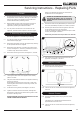
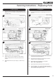
7. Main Injector
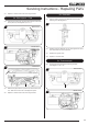
7.1 Undo the injector compression nut and bulkhead nut, see
Diagram 30, 31 or 32, arrows D and E, pull the pipe clear of
the injector body.
D
E
30
Manual Control
D
E
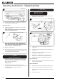
31
Remote Control
D
E
32
Slide Control
7.2 Rotate the injector until it is fully removed.
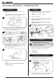
7.3 Replace with the correct replacement injector. When
ordering, always state the model, gas type and serial
number.
7.4 Reassemble and turn the gas supply on, check for any
leaks.
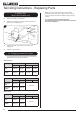
8. Mag Unit
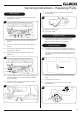
8.1 Undo the thermocouple nut, see Diagram 33, 34 or 35,
Arrow B.
B
33
Manual Control
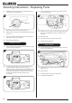
B
34
Remote Control
B
35
Slide Control
8.2 Undo the mag unit retaining nut at the back of the control
valve behind the thermocouple nut.
8.3 After removing the retaining nut, the mag unit can be
tapped out and a replacement fitted.
8.4 Replace the mag unit retaining nut and tighten.
Note - this is a gas-tight seal.
8.5 Replace the thermocouple and check for gas leaks.
8.6 After reassembly, carry out the flame failure functional
check as detailed in the Fault Finding chart, especially the
time it takes for the mag unit to close.