
Logic HE Balanced Flue Combined Controls Installation User Instructions

38
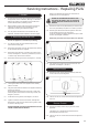
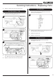
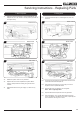
6.6 Rotate the piezo anti-clockwise until a tab appears in the
slot at the front, see Diagram 25.
Tab
Piezo
25
6.7 Withdraw the Piezo unit forward from the valve.
6.8 Replace with a new unit and re-assemble the valve into the
burner unit.
6.9 Check the operation of the Piezo ignitor making sure that
both ignition ‘clicks’ are functioning.
6.10 Reassemble the appliance.
Remote Control
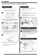
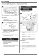
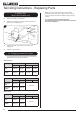
6.11 Undo the single screw that secures the left hand side of the
control cover, see Diagram 26.
26
6.12 To release the right hand side of the control cover insert
the narrow blade screwdriver into the slot shown in
Diagram 27, lever it gently and pull from the right hand side
at the same time. The cover will now come off, there is a
small cylindrical metal spacer inside the cover, this must
be kept and replaced on the fixing screw during
re-assembly.
27
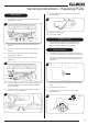
6.13 Disconnect the ignition lead from the gas valve and the
pilot, see Diagram 28.
28
Ignition
lead
6.14 Replace with a new ignition lead following the same route
as the old one. Replace the valve cover and the pilot
assembly.
6.15 Refit the burner.
6.16 Check the operation of the new ignition lead.
6.17 Reassemble the appliance.
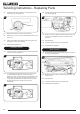
Slide Control
6.18 Disconnect the ignition lead from the ignition unit and the
pilot unit, see Diagram 29.
29
Pilot
Unit
Ignition
Unit
Ignition Lead
6.19 Replace with a new ignition lead following the same route
as the old one.
6.20 Refit the burner.
6.21 Check the operation of the new ignition lead.
6.22 Reassemble the appliance.
Servicing Instructions - Replacing Parts