
Logic HE Balanced Flue Combined Controls Installation User Instructions

37
Servicing Instructions - Replacing Parts
Slide Control
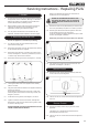
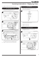
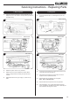
5.10 To remove the gas valve first remove the thermocouple,
see Diagram 19, Arrow A.
D
19
A
B
C
5.11 Undo the pilot pipe from the gas valve, see Diagram 19,
Arrow B.
5.12 Undo the inlet pipe from the gas valve, see Diagram 19,
Arrow C.
5.13 Undo the main injector feed pipe from the gas valve,
see Diagram 19, Arrow D.
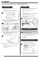
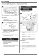
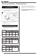
5.14 Disconnect the 2 leads from the micro-switch, see
Diagram 20.
20
Leads
Bracket
Micro-switch
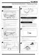
5.15 Undo the screw from the end of the spindle and remove the
bracket, see Diagram 21. Ensure the bracket is replaced
during reassembly.
5.16 Undo the 2 screws securing the bracket to the bottom of
the burner unit, see Diagram 21.
Screw
Screw
21
5.17 Undo 2 screws securing the gas valve to the bracket,
see Diagram 22.
Screws
22
5.18 Replace in reverse order.
5.19 Check for gas leaks.
6. Ignition Lead
6.1 The different control versions of this appliance have
different servicing requirements for the Ignition Lead.
Follow the relevant section for each product.
Manual Control
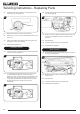
6.2 The Ignition lead and Piezo on this appliance are part of
one complete unit and must be replaced at the same time.
To replace the unit remove the control knob on the front of
the valve cover and undo the nut securing the valve, see
Diagram 23.
23
6.3 Disconnect all other valve connections on the rear of the
valve.
6.4 The valve will now come off.
6.5 Remove the clip from around the front of the valve,
see Diagram 24.
Clip
Ignition
lead
Piezo
24