
Logic HE Balanced Flue Combined Controls Installation User Instructions

33
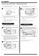
Refer to the separate decorative front instructions to
replace the front on the appliance.
UNDER NO CIRCUMSTANCES SHOULD THE
APPLIANCE BE USED IF ANY OF THE GLASS
FRAME RETAINING SCREWS ARE LOOSE OR
MISSING.
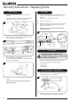
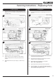
2.9 Remove the white stones (Stone Effect) or ceramic coals
and liners (Coal Effect) and place on a clean dry surface.
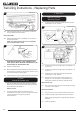
2.10 Remove glass frame seal from the appliance. Push the
arrow-headed spring clips out of the body.
It may be necessary to slightly compress the clips to ease
removal, see Diagram 2, Detail A.
NOTE: Only the lower seven clips need to be removed.
2
1
1
Detail A
2
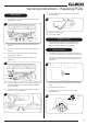
2.11 Fully remove the 2 lower outer fixing screws from the
appliance, see Diagram 1, Arrow A.
Manual Control
2.12 Remove the lower screw positioned centrally below the
control valve knob, see Diagram 3.
Posi screw
3
2.13 The burner unit can now be removed from the appliance,
see 2.20.
Remote Control
2.14 Remove the battery before carrying out work on this
appliance.
The battery box is located at the bottom left of the
appliance behind the ash cover.
2.15 The burner unit can now be removed from the appliance,
see 2.20.
1. General
1.1 All principal components can be replaced without removing
the appliance from its installation, although it is essential
that the gas supply to the appliance is turned off at the
isolation device before proceeding further.
1.2 Before replacing some of the components it will first be
necessary to remove the burner assembly from the
appliance by following the instructions below.
1.3 If for any reason the flue has to be removed from the
appliance, the seal must be replaced in the inner spigot.
2. Removing the Burner Unit
Ensure the appliance is cold before proceeding.
2.1 Turn the gas supply off at the isolation device. Then
disconnect the supply pipe.
2.2 Remove the decorative front from the appliance by referring
to the separate instructions supplied.
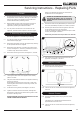
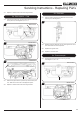
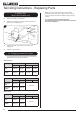
2.3 Remove the glass frame by unscrewing the 2 lower outer
screws, see Diagram 1, Arrow A, by several turns, there is
no need to fully remove these 2 screws.
2.4 Remove the remaining 6 screws, see Diagram 1, Arrow B.
B
B
B B
B
B
A
A
1
2.5 Lift the glass frame clear of the appliance and carefully
place to one side.
2.6 The glass frame must be refitted to the appliance following
cleaning or servicing.
Ensure that the fibre glass seal on the box is intact, then
lower the glass frame onto the 2 lower fixing screws, see
Diagram 1, Arrow A.
2.7 Fit the other 6 fixing screws, see Diagram 1, Arrow B.
2.8 Tighten all 8 screws to secure the frame, see Diagram 1.
Replace ALL of the securing screws ensuring that a screw
is present in all fixing slots.
NEVER OPERATE THE APPLIANCE WHEN THE GLASS
FRAME IS REMOVED OR BROKEN.
Servicing Instructions - Replacing Parts