
Logic HE Balanced Flue Combined Controls Installation User Instructions

23
Installation Instructions
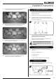
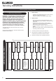
8A. White Stone Layout
ONLY USE THE CORRECT TYPE AND QUANTITY OF
WHITE STONES. ALWAYS FOLLOW THE FUEL BED
LAYOUT AS STATED IN THESE INSTRUCTIONS.
NEVER CHANGE THE LAYOUT FROM THAT SHOWN
HERE.
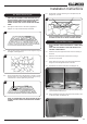
8.1 Arrange the white stones in the areas highlighted in
Diagram 11. They should be evenly distributed.
11
8.2 Lean the white stones against the burner ledges to disguise
the ledges, see Diagram 12.
12
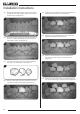
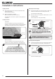
8.3 Check that the port area, see Diagram 13, Arrow A is clear
of white stones. This can be easily done by gently running
a screwdriver or similar object along this area.
A
13
NOTE: IT IS IMPORTANT THE WHITE STONES DO NOT
COVER THE PORT AREA IN BETWEEN THE BURNER
LEDGES.
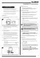
8.4 Ensure that no stones overhang or fill the pilot area, see
Diagram 14, Arrow B.
B
B
14
NOTE: STONES SHOULD NOT BE PLACED DIRECTLY
IN FRONT OF THE PILOT CROSS LIGHTING FLAME.
8B. Coal Effect Layout
NOTE: CERAMIC PARTS ARE FRAGILE. HANDLE WITH
CARE.
ONLY USE THE CORRECT TYPE AND QUANTITY OF
CERAMIC COMPONENTS.
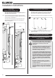
8.5 Place the rear panel against the rear of the box resting on
the shelf.
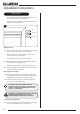
8.6 Slide one of the side panels into the box ensuring it
touches the rear panel.
8.7 Gently ease the front edge of the side panel behind the
flange so it lies flat against the wall of the box.
8.8 Repeat with the second side panel, see Diagram 15.
Left Right
15
8.9 Locate the top panel on top of the sides and rear by lifting it
up and forward inside the box.
8.10 Slide it backwards and down behind the side panels to rest
on the rear panel, see Diagram 16.
16