
Reflex 75T Conventional Flue User Installation Manual


41
Servicing Instructions - Replacing Parts
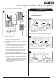
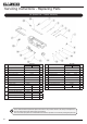
11.6 Remove the 8 way cable from the Control Box.
8 Way
Cable
Interrupter Leads
Ignition lead
LED Lead
29
Module
Lead
Solenoid
Lead
Thermocouple
Pilot Pipe
Control
Box
Module
Solenoid
11.7 Replace in reverse order.
After replacing the Control Box ensure that all cable
connections are refitted, see Diagram 29.
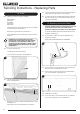
11.8 After replacing the Control Box you will need to reprogram
the handset.
— Press and hold the reset button on the control box until
you hear two signals. After the second longer signal:
— Release the reset button and within 20 seconds:
— Press the DOWN button on the handset until you hear
two additional short signals confirming the new code
is set. If there is a single long signal the code learning
sequence has failed or the wiring is incorrect.
Note: When pressing the DOWN button on the handset
if two beeps are not heard:
— Release the DOWN button and CONN will be displayed
on the handset screen. An 8 second count will
start on the handset screen followed by two short beeps
conrming the new code is set. If there is a single long
signal the code learning sequence has failed or the
wiring is incorrect.
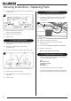
12. Fuel Bed Injectors
This appliance has 6 Fuel Bed Injectors.
NOTE: The injectors are not identical, see Page 12.
TO ENSURE CORRECT ASSEMBLY REPLACE EACH
INJECTOR INDIVIDUALLY.
30
12.1 Remove the Log Burners and Mesh Tray,
see Section 4.
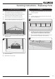
12.2 Remove the 2 nuts and lock washers from each Burner
Bracket, see Diagram 31.
31
12.3 Remove the Gasket, see Diagram 32.
32
Gasket