
Reflex 75T Conventional Flue User Installation Manual

40
Servicing Instructions - Replacing Parts
8. Ignition Lead
8.1 Remove the Log Burner, Mesh Tray, and Air Guide,
see Section 4.
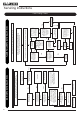
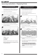
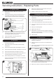
8.2 Disconnect the Ignition Lead from the Electrode, lift the
Control Box from the Velcro pads and pull forward to
expose the Ignition Lead and remove, see Diagram 26.
26
Ignition Lead
8.3 Replace with a new Ignition Lead following the original
route. Ret the Vidaex cover over the lead. Ensure the
cover engages fully over the Electrode.
8.4 Check the operation of the new Ignition Lead.
8.5 Reassemble in reverse order.
9. Gas Valve
To change the gas valve:
9.1 Remove the Log Burners and Main Control Assembly,
see Section 4.
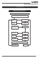
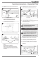
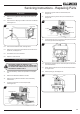
9.2 Disconnect the Gas Inlet Pipe, see Diagram 27, Arrow A.
9.3 Disconnect the Gas Outlet Pipe, see Diagram 27, Arrow B.
9.4 Disconnect the Pilot Pipe, see Diagram 27, Arrow C.
9.5 Disconnect the Thermocouple, Thermocurrent Wires and
the Interrupter Block, see Diagram 27, Arrow D.
9.6 Remove the Eight Wire Loom, see Diagram 27, Arrow E.
There is an access hole in the top of the Control Bracket to
release the locking tab.
C
D
A
B
E
27
Screw
Screw
9.7 Remove the 2 screws securing the Valve to the support
bracket and withdraw the Valve.
9.8 Replace in reverse order and check for leaks.
10. Magnetic Safety Valve
10.1 Remove the Log Burners and Main Control Assembly,
see Section 4.
10.2 Undo the Thermocouple from the Interrupter Block and
remove the 2 Interrupter Leads.
10.3 Unscrew the Interrupter Block from the back of the Valve.
10.4 Undo the silver Magnetic Valve retaining nut on the back of
the Valve.
10.5 Gently tap out the Mag Valve.
10.6 Replace with a new unit.
10.7 Reassemble in reverse order ensuring that the interrupter
leads are connected correctly with the blue tag lead furthest
away from the gas valve body.
10.8 Check for leaks.
11. Control Box
11.1 To replace the Control Box first remove the Main Control
Assembly, see Section 4.
11.2 Release the cables from the clip on the underside of the
assembly.
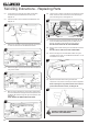
11.3 Disconnect the Module and Solenoid leads from the Control
Box, see Diagram 28.
28
Module Lead
Solenoid
Lead
11.4 Pull the Control Box forward and remove the Ignition Lead.
The Control Box is held on by Velcro pads.
11.5 Remove the 2 screws to remove the 2 Interrupter Leads.