
Reflex 75T Conventional Flue User Installation Manual

36
3. Removing the Fuel Effect
The fuel effect consists of 6 different components.
To avoid damage Logs A, B, C and D should be removed in
the following order and placed on a dry, clean surface.
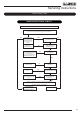
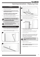
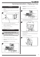
3.1 Remove the Log D, see Diagram 5.
3.2 Remove Log B from the Log Burner, see Diagram 5.
5
B
C
D
3.3 Remove Log C from the Log Burner, see Diagram 5.
3.4 Slide Log A backwards, from under the centre Log Burner,
to remove, see Diagram 6.
6
A
3.5 Remove the remaining components:
1. Log E.
2. Embers F, G and H.
2. 2 small Embers.
3. Shale Effect.
4. Amber Effect.
Keep each component separate for ease of replacing.
When replacing the fuel effects see Installation Section
11 for layout instructions.
4. Removing the Log Burners
and Main Control Assembly
4.1 To remove the decorative front from the appliance please
refer to the separate instructions supplied.
4.2 Remove the Glass Frame, see Section 2.
4.3 Remove the Fuel Effect, see Section 3.
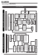
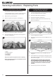
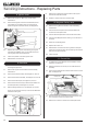
4.4 Remove the 3 M4x6 screws from the base of the 3 Log
Burners, see Diagram 7.
7
Screws
4.5 Lift the 3 Log Burners to remove.
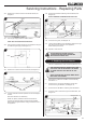
4.6 Remove the 2 screws from the front of the Mesh Tray, see
Diagram 8.
8
Rear Screws
Front Screws
4.7 Loosen the 3 screws at the rear of the Mesh Tray, see
Diagram 8.
4.8 Slide the Mesh Tray forward slightly to disengage from the
rear screws and carefully lift over the Log Burner Brackets,
Pilot and Cross Lighter.
WHEN REPLACING THE MESH TRAY TAKE CARE
NOT TO DAMAGE THE LOG BURNER BRACKETS,
PILOT AND CROSS LIGHTER. REPLACE THE FRONT
SCREWS FIRST BEFORE TIGHTENING THE REAR
SCREWS.
4.9 Remove through the front of the appliance.
Servicing Instructions - Replacing Parts