
Reflex 75T Conventional Flue User Installation Manual

29
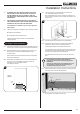
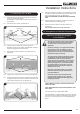
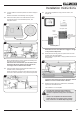
14.2 Lift and rotate the Air Guide upwards from the front edge to
remove.
Note the orientation for reassembly of the air guide.
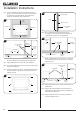
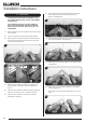
14.3 Secure the velcro pads to the underside of the Wi-Fi
module and position in the allocated position, see
Diagrams 56 & 57.
56
LED'S
57
When satisfied with the position remove the backing from
the velcro pad and secure in place.
Ensure the Wi-Fi module butts up to the folded return
beside the LED bar & clearance is left between the
front edge of the fire and the Wi-Fi module.
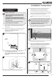
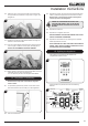
14.4 Using the Wi-Fi cable Connect the Wi-Fi module to the
receiver module, see Diagram 58.
Gazco recommend running the cable along the front edge
of the fire to avoid obstruction of any internal components.
58
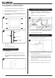
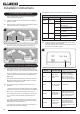
14.5 This should complete the wiring circuit as shown, see
Diagram 59.
Wi-Fi
Router
Interrupter Leads
Wi-Fi Module
AUX Lead
59
Valve Lead
Ignition
Cable
Connecting Wire
Lighting
Module
Mains
Lead
Smart Device
Wall Switch Lead
(not applicable)
NOTE: Ensure none of the wires are snagged or caught
on any internal components.
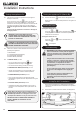
14.6 Rotate and slide the air guide into position with the ends
locating under the side brackets.
Ensure that the angled metal is sloping towards the front of
the appliance.
60
Follow the steps listed in the MyFire App Setup manual
PR2467 to connect a smart device to the fire.
14.7 Replace the Decorative Front, Glass Panel, Fuel Effect,
Log Burners and Mesh Screen.
The installation is now complete.
Once the Wi-Fi module has been installed and
connected to a power source there is a 24 hour
window to complete the setup process on the MyFire
app.
If setup is not completed in this window the Wi-Fi
module will have to be manually reset to complete
setup, see Section 16 & PR2467 MyFire App Setup.
Installation Instructions