
Reflex 75T Conventional Flue User Installation Manual

27
Installation Instructions
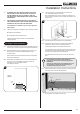
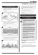
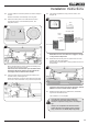
11.11 Place the Log D on the left hand side of the fuel bed with
the right hand end positioned in the groove on Log A, see
Diagram 50.
50
D
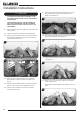
11.12 Spread the remaining amber effect between the logs and
embers to cover the fuel bed.
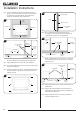
11.13 Lean the 2 small embers against the bar, either side of the
front of Log B, to hide the Cross Lighter, see Diagram 51.
DO NOT PLACE EMBERS OVER THE BURNER.
51
11.14 Evenly spread a small amount of the shale effect across the
mesh bed to ll any gaps, see Diagram 51.
It is not necessary to use all the supplied Shale Effect.
12. Completion of Assembly
Ensure that the rope seal on the back of the glass
frame is intact.
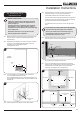
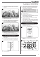
12.1 To replace the glass frame, position so the hooks on the
back of the frame t over the side pins, see Diagram 52.
52
12.2 Push the handle down.
12.3 Replace the screws. As the screws are tightened the glass
frame is pulled down against the hooks and forms a seal.
Replace ALL of the securing screws ensuring that a
screw is present in all xing slots.
UNDER NO CIRCUMSTANCES SHOULD THE
APPLIANCE BE USED IF ANY OF THE GLASS
FRAME RETAINING SCREWS ARE LOOSE OR
MISSING.
12.4 Replace the lower trim.
12.5 Replace the 2 magnetic side trims.
NEVER OPERATE THE APPLIANCE WHEN THE GLASS
PANEL IS REMOVED OR BROKEN.
12.6 Replace the decorative front by referring to the separate
leaet supplied with the front.
NOTE: ENSURE THAT THE LOGS ARE POSITIONED AS
ABOVE. ONLY USE THE CORRECT AMOUNT OF LOGS
AS SPECIFIED IN THE DIAGRAMS.
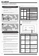
13. Lighting the Appliance
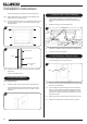
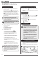
The appliance is operated by thermostatic and
programmable remote control.
53
Via the remote it is possible to control the following
features:
54
Child proof
lock
Time
Light
EcoFlex
Mode
Signal
Indicator
Thermostatic
Mode
Dual Burner
Fucntion
Temperature
Program
Mode
Countdown
timer
Battery
Status