
Reflex 75T Conventional Flue User Installation Manual

26
Installation Instructions
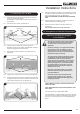
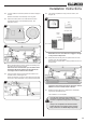
11. Log Layout
LOGS MUST BE POSITIONED ACCORDING TO THE
FOLLOWING INSTRUCTIONS TO GIVE THE CORRECT
FLAME EFFECT.
THE 3 BURNER LOGS MUST LOCATE CORRECTLY
ONTO THE LOG BURNERS. ENSURE THE AMBER
EFFECT DOES NOT CAUSE THE LOGS TO LIFT OFF
THE BURNER.
11.1 Ensure the Burner Tray and Log Burners are clean and free
from any debris.
11.2 The main components are clearly individually labelled.
11.3 Place Log E on the right hand side of the fuel bed with the
left hand end positioned under the rear of the right hand
Log Burner, see Diagram 44.
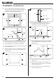
44
E
H
G
F
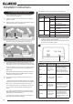
45
EMBER H
EMBER G
EMBER F
11.4 Place the cutout of Ember G against the left hand Log
Burner bracket, in the position shown in Diagrams 44
and 45.
11.5 Place the cutout of Ember H against the centre Log Burner
bracket, in the position shown in Diagrams 44 and 45.
11.6 Place the cutout of Ember F around front of the Pilot,
see Diagrams 44 and 45.
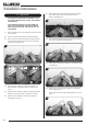
11.7 Evenly spread some of the amber effect across the mesh
bed, leaving space under the lower edge of the Log
Burners, see Diagram 46.
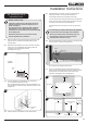
46
11.8 From the back carefully slide Log A under the left hand side
of the centre Log Burner, see Diagram 47.
47
A
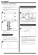
11.9 Place Log B on the centre Log Burner in the position shown
in Diagram 48.
48
B
11.10 Place Log C on the right hand Log Burner in the position
shown in Diagram 49.
Note: There should be a ngers width between Log C and
Log E.
49
C
B