
Reflex 75T Conventional Flue User Installation Manual

24
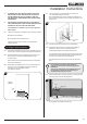
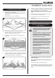
Ensure the clearances are maintained, see Diagram 20.
6b.8 Apply plasterboard to the remainder of the studwork and
plaster the front face of the board.
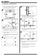
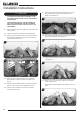
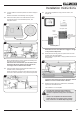
6b.9 Secure the appliance to the non-combustible board through
the 6 xing holes, using the anchor xings provided, see
Diagram 36 & 37.
36
37
Appliance Edge
Appliance Flange
Non-combustible
Board
Fixings
6b.10 Install the decorative front referring to separate installation
instructions.
To nish installation see 6.7.
To Finish the Installation
After commissioning:
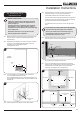
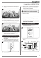
6.7 Finish the sides of the chimney breast, see Diagram 38.
A removable access hatch must be left in the side of the
chimney breast for future servicing and inspection of the
appliance.
38
Installation Instructions
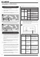
7. Fitting the Main Control Assembly
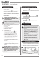
7.1 Carefully lower the Main Control Assembly into the
appliance and slide slightly to the left to engage with the
studs.
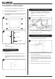
7.2 Replace the 2 wing nuts, see Diagram 39.
39
Mains Lead
2 Wing Nuts
7.3 Reconnect the Mains Lead to the Module, see Diagram 39.
7.4 Connect power to the appliance.
8. Gas Soundness Pressure Check
8.1 Connect a suitable pressure gauge to the test point located
on the inlet tting. Turn the gas supply on.
40
Elbow
8.2 Remove the xing screws and loosely place the appropriate
burners onto the injectors.
8.3 Light the appliance and check all gas joints for possible
leaks. Turn the appliance to maximum and check that the
supply pressure is as stated on the databadge. Turn the
appliance off. Replace the test point screw and check the
test point for leaks.
8.4 Remove the burners. Take care as the burners will be hot.
8.5 Replace the access panel, securing with the 2 screws.