
Reflex 75T Conventional Flue User Installation Manual

21
Installation Instructions
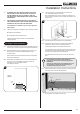
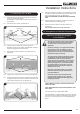
6.4 ALTERNATIVELY FOR THE HIGH VENTILATION THE
ENCLOSURE CAN BE CONSTRUCTED TO LEAVE A
GAP BETWEEN THE TOP OF THE WALL AND THE
CEILING GIVING THE REQUIRED VENTILATION AREA
OR GREATER.
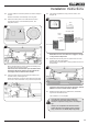
6.5 AN ACCESS HATCH MUST BE LEFT IN THE SIDE OF
THE CHIMNEY BREAST FOR FUTURE SERVICING AND
INSPECTION OF THE FLUE AND APPLIANCE.
This installation is Top Exit only. Use only a rigid twin
wall ue pipe.
6.6 There are 2 methods of installation into a studwork chimney:
6a. Edge nish Installation.
6b. Installation with a decorative front.
Carefully read the relevant section for the installation
method required.
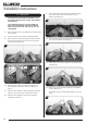
6a. Edge Finish Installation
6a.1 This method is designed so that non-combustible board can
be taken right up to the edge of the ange of the appliance.
6a.2 Build the studwork chimney breast and enclosures to the
desired size to include the protected platform at the
required height.
Ensure that the minimum 200mm distance to combustible
studwork is maintained.
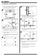
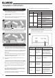
6a.3 Before tting the cladding, cut 2 x 200 x 100mm minimum
holes in the non-combustible side boards to allow air
circulation around the appliance vents,
see Diagrams 22 & 23.
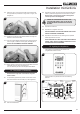
22
25mm
min
12mm min
100
200
Front of
Studwork
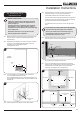
6a.4 Line the aperture for the appliance with 12mm thick
non-combustible material as shown.
Non-combustible board used to protect the studwork can
line the aperture inside the 50mm clearance distance, see
Diagram 23.
23
Non-combustible
board
6a.5 Site the appliance and decide on ue requirements.
6a.6 Prepare the ue connection using the chosen method
described in Section 2 ensuring that distances to
combustible materials are maintained at all times.
Connect the ue and install the appliance into the aperture.
At the same time ensure that the gas pipe passes through
the silicon panel at the back of the appliance.
Provide electric services into the void on the right hand
side.
It is necessary to be able to disconnect the
appliance from the mains electrical supply after
installation.
This may be achieved by an accessible plug or by
incorporating a switch into the fixed wiring in
accordance with the rules in force.
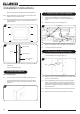
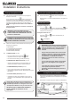
6a.7 Slide the metal plate, previously removed, over the gas pipe
and secure with a screw, see Diagram 24.
24
Screw
Metal Plate
Gas Supply
Do not secure the appliance at this time.